A PCB ruler is a common promotional item, or design exercise. Usually they have some sample outlines and holes as an aid to PCB design, but sometimes they also incorporate some circuitry. [Clovis Fritzen] has given us an ingenious example, in the form of a PCB ruler with a built-in thermometer.
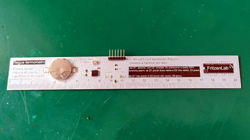
This maybe doesn’t have the fancy seven segment or OLED display you were expecting though, instead it’s an ATtiny85 with a lithium cell, the minimum of components, a thermistor for measurement, and a couple of LEDs that serve as the display. These parts are interesting, because they convey the numbers by flashing. One LED is for the tens and the other the units, so count the flashes and you have it.
We like this display for its simplicity, we can see the same idea could be used in many other places.On a PCB ruler, it certainly stands apart from the usual. It has got plenty of competition though.


Neat enough as a project. Some component slimming/simplification:
ATtiny chips have a built in voltage reference at ~1.1 v – you can measure that versus the unknown supply and find the supply (battery) voltage (with a correction for whatever the 1.1v is precisely). No resistor divider needed.
Second, there’s an on-chip temperature sensor – absolutely not very good,(+/-10C) but close enough for room temperature work with a single point calibration.
Bonus points – both are improved if you can correct for the bandgap reference vs temperature curve – but you’ll have to do some real multipoint characterisation.
Author here. Thanks for the tip on the 1.1V reference, did no know that.
*not
As a ruler already has graduated markings, I was expecting a secondary scale with LEDs along the length of the ruler. For some reason.
A ruler with tiny LEDs – or even made from strip of e-ink? – that can, at the press of a button, switch from being marked in cm/mm, to inches & fractions thereof.
And if that seems daft/pointless, in my defense, I must stop reading Hackaday before my morning coffee has kicked in.
Now you can normalize the measurement by generating a coefficient to compensate for thermal expansion.
Every ruler is a thermometer, you just need a way to measure its length. :*)
You can pry my Invar ruler from my cold hands! Or hot ones! Makes no difference!
Actually, I did have an application once where an Invar ‘ruler’ DID have too much tempco. Fixed that by a ‘shim’ of a brass screw: adjusted the zero point by how much brass protruded.
(this application had a precision of 1 part in 10^11 and absolute accuracy of better than 1 in 10^9. That Invar cavity even after brass correction was still a large part of that absolute error budget.)
Another (possible) improvement is to replace the blinky blinky with a binary or BCD display:
pin 2 is free, use that as a third LED pin, then connect the 3 pins using charlieplax, allowing for 6 LEDs.
Use the 6 LEDs to either display binary (1,2,4,8,16,32) or BCD (1,2,4,8,10,20).
A BCD display would limit it to 0..39 degrees, as opposed to your current 0..49 degrees, but the binary one would allow 0..63 (or -32..31 if using two’s complement).
Using another pin (using the internal voltage reference as suggested) would allow for 12 LEDs, almost enough for a full 2x7segment display (made with discrete LEDs of course)
Again, when dropping segement F on the tens and combining segements A, D, and G into a single one, you could get away with this, even having one LED to spare for a negative, allowing -29..29 degrees.