Current measurements are not as handy as voltage measurements. You typically need to either measure the voltage across something and do some math or break the circuit so a known resistor in your instrument develops a voltage your meter measures and converts for you. However, it is possible to get non-contact current probes. They are generally pricey, but [Kerry Wong] shows us one under $200 and, thus, budget compared to similar probes. Check out the review in the video below.
The OWON unit has three ranges: 4 A, 40 A, and 400 A. It claims a resolution of 10 mA and a bandwidth of 200 kHz. It requires a 9 V battery, which [Kerry] suspects won’t last very long given the rated power consumption number, although the measured draw was not as high as claimed. The specs aren’t great — this seems to be little more than a current probe meter with a connector for an oscilloscope, but if it meets your needs, that could be acceptable.
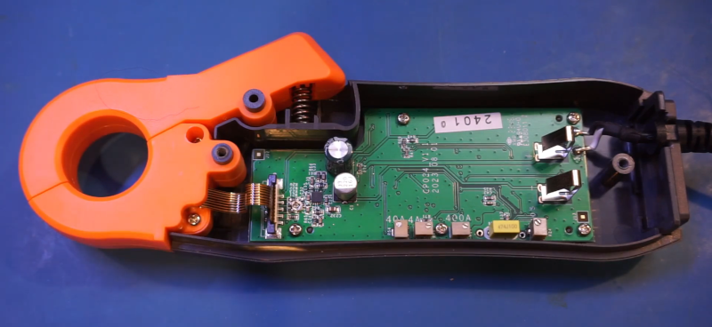
Stay tuned for the end if you want to see the insides. There’s not much on the PCB’s top side. There’s a hall-effect sensor, some adjustment pots, and an op amp. The other side of the board has many more components, but the circuit is purely analog.
It made us wonder if we should nip down to the local cheap tool store and buy a $40 meter with similar specs. It seems like you could find a spot to tap a voltage from that and save quite a bit of money.
It is possible to create a probe that doesn’t break the bank and manages at least 2 MHz of bandwidth. Or, make your own for about $25, although we can’t vouch for the specs on that one.


Well, if one ditches the oscilloscope current probes can be gotten pretty cheap.
We use the current probe in our automotive diagnosis for starters, alternators, electric motors, solenoids, injectors, ignition coils, and identifing mechanical engine problems. They allow us to look at current and voltage signals to determine if the circuit is actually working and find reasons why things are not working as expected. In our opinion without the current probe our job would be much more difficult and full of inaccurate diagnosis.
Any recommendations on a DC current clamp meter that is somewhat accurate in the milliamp range? My friend is a mechanic and wants to measure the “quiescent” current in cars, and in some models that can be down in the tens of mA, so my 600A clamp meter didn’t do much good.
The UNI-T UT210E? Resolution of 1 mA in the 2A measuring range. Costs about €50.
I own one, bought it when I saw it in one off Great Scott’s video’s.
It’s a great little meter – not many around that can do DC measurements that low. Only slightly annoying thing is that you have to take care in zeroing the meter on the DC ranges, and also be careful not to move it, since the Earth’s field is quite sufficient to give a reading if you change the orientation of the meter.
I glued a piece of EVA foam onto the inside surface of each side of my current clamp.
The clamp still fully closes.
This way, the wire being measured is held in roughly the same spot during a measurement.
It gets chewed up after a while. But it helps some and it is trivially easy and cheap.
Fluke has a clamp meter (771?) for 4-20mA loops if this does the job for you.
I gave up trying to find a clamp on meter for this exact task, was always an exercise in frustration as I couldn’t trust the readings, always go back to ol’ trusty, a little ammeter with a 10a. Fuse inline and long leads so I can see it while lying under a dash etc. clamp meters seem to really struggle with low current DC. Even the good ones.
For draws that low you’re always going to be better off using a regular multimeter, I suspect even the best current clamps would struggle to achieve that level of accuracy outside of a lab environment.
Current clamps are more suited for the broad strokes large current stuff.
There are tables with the mv drop per amp calculated for various automotive fuses.
example: hthtps://m.roadkillcustoms.com/wp-content/technical-pdf/Standard%20ATC%20Fuse%20Voltage%20Drop%20Chart.pdf
I guess you could increase the accuracy of that by measuring resistance of the exact fuse in the circuit you’re looking at or by installing your own instrument-grade fuse