If you want to measure AC or DC current with an oscilloscope, a current clamp is a great way to do it. The clamp surrounds the wire, so you don’t need to break the connection to take your measurements. These used to be expensive, although we’ve seen some under $100, if you shop. We don’t know if it was cost or principle that motivated [Electronoobs] to build his own current clamp, but he did.
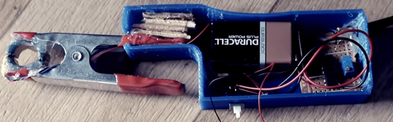
This probe design is little more than a 3D printed case, an old power supply toroid, and a conventional alligator clamp to make the business end. The sensor uses a ferrite core and a hall effect sensor. The ferrite toroid is split in half, one half in each side of the clamp. An opamp circuit provides a gain of 100 to boost the hall effect sensor’s output.
In addition to building a homebrew probe, the video also shows a teardown of a Hantek current probe and explains the theory behind the different kinds of current probes, including some tricks like using a compensation winding to prevent core magnetization.
Does it work? You bet. After calibration, it did just fine. It’s not as pretty as a $100 unit, but beauty is in the eye of the beholder, and we are suckers for homebrew gear so we will say it is certainly more interesting. If you have a fair junk box (and a 3D printer), this probe could be made very inexpensively. The hall effect and a BNC connector are likely to be the most expensive parts. Even if you bought everything and used a non-printed case, we would be hard-pressed to think you’d spend more than $25.
If you want to see how the big boys do it, Keysight had a good break down last year. We’ve seen other homebrew builds for current probes and some of them are very accurate.


Published in Silicon Chip September 2003, it’s hardly an original invention.
http://tronixstuff.com/2011/04/12/kit-review-current-clamp-meter-adaptor/
http://archive.siliconchip.com.au/cms/A_30669/article.html
I don’t think that they claimed to be the original, so…?
It’s new to me, and although I already own a few it’s pretty cool to see a break down like this, so thanks to HAD.
There’s nothing new under the sun. That doesn’t mean there isn’t anything neat to read about under the sun.
Yup… pure true to life hacking! And if I duplicate his work exactly, I’m hacking! If it was something totally new, that would be inventing, but someone then copying it to have their own would be hacking!
Would an AC filter toroid work? I’ve got lots laying around and they’re already wound on both sides.
An easy way to get more bandwidth and accuracy out of something like this is to put the output winding around the toroid with 100 turns (or whatever ratio you’re trying for) and use a higher gain integrator for the op-amp circuit. This then tries to keep the core at zero flux at low frequencies which helps remove the core and hall sensor nonlinearities. It also means the winding itself does the transformation at high frequencies so you’re not limited by the bandwidth of the opamp. This, along with fancy shielding and compensation, is how the expensive 100MHz bandwidth current probes work.
easy to use and very professional. I bought come clamp meter in Bangladesh from fluke agent in bd. when I bought fluke clamp meter for measure AC and DC current it really works very nicely. Surely the best brand for maintenance. I am always visiting your site and fluke.com.bd site both site are very helpful for me.
I enjoyed this video. Thank you. Now I’m thinking to duplicate this one for my own test circuit. But I have a question, if someone will teach me my question. What I want to know is how many frequency of the current can be measured with this clamp probe. What kind of factor of the probe may curb on the frequency of the current. I know an OP amp have a Band width voltage to amplify. I’m not sure the characteristic of the probe.
Thanks in advance
Will this ferrite core work? https://www.amazon.com/dp/B07YJWGFKZ/?coliid=I1PC8MM7SUFKU2&colid=1Y1FG92OMK4E8&psc=1&ref_=lv_ov_lig_dp_it
It’s a split core in a plastic case that latches. Is this correct?
Suppose you want a permanent probe. Why not use a solid toroid of ferrite? Why not wind. The coil AROUND the wire under test?
How about converting an off-the-shelf clamp meter such as ANENG PN103 to an oscilloscope?