It is a well-known reality of rescuing certain older electronic devices that, at some point, you’re likely going to have to replace a busted capacitor. This is the stage [Kevin] is at in the 3rd installment in his saga of reviving a 50-year-old Military Tektronix oscilloscope.
[Kevin] recently discovered a failed capacitor in the power supply for this vintage analog scope. Having identified and removed the culprit, it was time to find a way to replace the faulty component with a modern equivalent. The original capacitor is out of fashion to the degree that a perfect replacement would be impractical and likely not desirable. This job would call for a bit of adaptation.
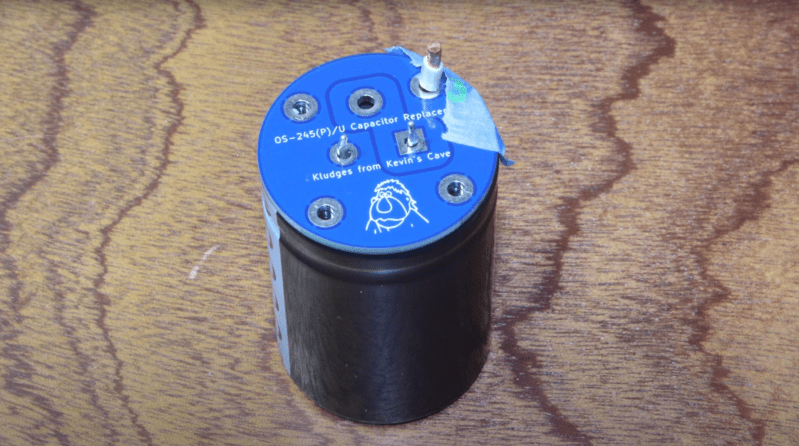
Starting with the recently desoldered pads on the power supply board as a template, [Kevin] walks us through his process of transferring his meticulously acquired measurements to KiCAD for the purpose of creating an adapter PCB. Once the original pads are mapped, he then draws in pads matching the leads of the new component, referencing the manufacturer’s schematic of the replacement part.
With everything drawn in place and design rule checks satisfied, it’s a quick turnaround from the PCB fabricator before this Tektronix scope moves one step closer to happy tracing again.
While the end product of this kludge is about as simple of a PCB as you might imagine, [Kevin’s] documentation is a thorough tutorial on the process for retrofitting components via adapter boards, covering some of the subtleties that you might miss if you’ve never been through it before.
We are looking forward to the next installment of Kevin’s undertaking. In the meantime, you can delve into other oscilloscope repair projects, here, here and here, or go deep on why capacitors fail as in the capacitor plague of the early 2000s (though these are not the same vintage or necessarily the same reason for failure as in [ Kevin’s ] device).


“The original capacitor is out of fashion to the degree that a perfect replacement would be impractical and likely not desirable.”
Old building with old breakers. Definitely not made anymore.
Style points would have been putting the assembly into the case of the old cap.
Almost expected by some vintage electronic enthusiasts.
I did that once. I have no desire to ever do it again. I was finding bits of tar around my workbench for a long time afterwards.
Hi, I’m the Kevin in the article.
I’d have paid more attention to original appearance, except that I have reason to believe that the failed capacitor is not original. (Discussed in a previous episode in the series.) I found only a couple of modern caps that might do the job that were narrow enough to fit inside. The newer ones are shorter and squatter than the vintage ones. Except for that, a 50-volt aluminum can capacitor doesn’t look all that different today from what it was fifty years ago!
tektronix capacitor adaptors have been availabe on ebay for years, by the way… even ordered some…
Yeah, the recap kit for the 7000 series would probably have worked. But I actually wanted to do the tutorial, because once in a while you have to adapt something that isn’t on eBay. My channel is more about teaching than showing off projects.
Nice, I’ll have to remember that.
Printing a whole PCB for this is overkill, but I suppose one has to do something more than dead-bug a modern smaller capacitor underneath the chassis (while leaving the original can in place of course) for such a thing to be article-worthy. Some would put it inside the original can, but even for multi-caps I’ve found it very easy to simply cut some leads and dead-bug three or four new electrolytics underneath. There’s always massive amounts of space.
Except leaving the old leaky capacitor in place can kill tubes quick smart with the DC leakage, and putting the new capacitor in place of the old doesn’t look like a complete 2nd rate bodge like tacking caps underneath does…
Except you dont do any of that.
You gut the old cap, install a new cap inside the old caps skin and reinstall.
Looks original.
There were NOT massive amounts of space. A 50-volt aluminum can capacitor today is about the same diameter (and half the height) of a 50-year-old one. That board had a veritable forest of electrolytics, with +/-150V, +35V, +/-15V and +5V supplies on it. It’s crowded, and there’s another board (or rather another card cage) right above it. Tek was smart, mounting the caps head down – if they do leak, they won’t spew electrolyte over innocent electronic bystanders.
Being able to spin up a custom PCB is an incredibly useful skill especially for repairing old gear. You can’t beat the reliability of solid solder connections compared to bodges, you can’t beat the aesthetic and flexibility of being made for exactly what you need.
Not groundbreaking by any means, but a great skill to have in your toolkit, and this is a great topic to tell new people about custom PCBs in an accessible first project.
In Software Engineering the newer replacement parts always seem to bigger than the originals.
Now that’s alliteration