Your design task, should you decide to accept it: given an input voltage, square it. Ok, that’s too hard since squaring 8 volts would give you 64 volts, so let’s say the output should be 10% of the square, so 8 volts in would result in 6.4V. How do you do it? [Engineering Prof.] knows how and will show you what you can do in the video below.
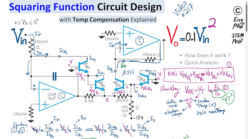
The circuit uses two op amps and some transistors. However, the transistors are used in a way that depends on the temperature, so it is important to use a transistor array so they are matched and will all be at the same temperature.
The math depends on the fact that the transistor response has a natural log term in it, and the property that the sum of two logs is the same as the log of the product of the numbers.
Because of the matching transistors, many of the terms in the equation cancel out. Because the transistors are current devices, the transistor circuit’s output current is the input current squared divided by the output transistor’s collector current. Then it is just a matter of converting the voltage to a current and back again using the right scaling.
There’s more to it, of course, but that’s the gist of it. You can dig into the math by watching the video. If the KCL references are fuzzy for you, here’s a refresher. Squaring a voltage would be pretty important for an analog computer.


If you want to use transistors, an LM394 is the way to go. Motorola used to make an analog multiplier IC; not sure if they still do.
LM394 was one I wasn’t familiar with so I looked up the datasheet. The datasheet gives circuits to do both a square root and a squaring function! Neat. Thanks.
As for four quadrant analog multipliers, I looked into those a few years back when looking into a analog Lorenz attractor simulator. They’re still made by Analog Devices and low spec ones will be about $20. I ended up writing a Lorenz attractor in javascript using the p5 library instead.
I used that exact squaring core (but with a current out, not voltage) in a Ku band PiN diode attenuator to control satellite uplink power (~1989 perhaps?). The shunt PiN diode attenuation varied non-linearly with the current, become less sensitive (in terms of dB/unit current) at higher currents; this circuit compensated for that and allowed me to get a roughly constant dB per DAC step from my 12 bit DAC.
BTW, higher resolution DACs were prohibitively expensive back then.
I think I used an LM3046 for the matched transistors.
I didn’t spot it in my quick run through the video, but that circuit really needs protection diodes for the BJT BE junctions, to prevent damage if the opamp outputs (for whatever reason) go to the wrong rail.
Looking at THAT 300P14-U, ADI MAT14ARZ-R7 and friends at 10+ bucks each, this starts smelling a lot like strapping needle probes to your 3D printer to turn it into a transistor binning device, heated bed and all.
Well, that would be a good hack.
Beautiful idea!
The MC1496 appears to still be in production, but it requires a lot of additional parts to make it useful as a voltage squarer.
Didn’t Bob Pease do this many years ago?
What didn’t he do?
The circuit appeared in an old National Semiconductor app note, so that’s plausible.
https://www.ti.com/lit/an/snoa626b/snoa626b.pdf
Page 21. Application note is from: July 1979 – Revised May 2013
AN is for the LM394 mentioned earlier in this thread by Peter.
Much more trivially done with a multiplier IC such as the AD633.
Multiple examples of one wired as a squarer here:
https://www.glensstuff.com/sprottsystems/sprottsystems.htm
Hello .
I share something i know about a electrical circuit. The formula just showing how each components behaviour in time (voltage -Amp digram ). How ever i some trick which is not tell in the video .the first one is Cap behaviour when puting in the input of a component. The second is Res and Ground puting between a layer or in the input of a component.
This is less mention in circuit and in some explanation video . however it take a important role in properties of a component.
Like you can make a square wave with 2 BJT , but have you ever wonder why author put a cap or res between of 2 BJT ? .
And some trick that i know . a diagram for one component iz quite simple but when puting a Res or cap it change the shape of a diagram significantly, this behaviour repeated when adding a new component or changing input value . So the question here , which math operator describe the phenomenon.
And at this point , how i program it at general case to predict a wave distribution?
When learner come here , they will understand entire advance topic in further and design their own circuit. Input and output is Crucial key.
If you’re really interested in circuits like this, I recommend this book chapter https://digital-library.theiet.org/doi/10.1049/pbcs002e_ch2
Authored by Barrie Gilbert (of Gilbert cell fame), this talks about the general principles of such circuits, and even shows how to produce trig functions of inputs.
The rest of the book is also excellent.
I miss having the modern equivalent of print editions of the old National and other application note books. I used to grab a book when I had a spare moment and leaf through the app notes looking for things I hadn’t learned. I believe I got more much from that than any of the formal coursework I took.
I just isn’t the same Google-searching. The benefit of the physical book was the serendipity of running across things which you didn’t realize you needed to know in advance. You don’t get those accidental revelations doing web searches.
Now we just browse Hackaday :-)
Challenge (Advanced): Now do it accurately and consistently over a range of temperature.