
It is hard to get very far into electronics without knowing Ohm’s law. Named after [Georg Ohm] it describes current and voltage relationships in linear circuits. However, there are two laws that are even more basic that don’t get nearly the respect that Ohm’s law gets. Those are Kirchhoff’s laws.
In simple terms, Kirchhoff’s laws are really an expression of conservation of energy. Kirchhoff’s current law (KCL) says that the current going into a single point (a node) has to have exactly the same amount of current going out of it. If you are more mathematical, you can say that the sum of the current going in and the current going out will always be zero, since the current going out will have a negative sign compared to the current going in.
You know the current in a series circuit is always the same, right? For example, in a circuit with a battery, an LED, and a resistor, the LED and the resistor will have the same current in them. That’s KCL. The current going into the resistor better be the same as the current going out of it and into the LED.
This is mostly interesting when there are more than two wires going into one point. If a battery drives 3 magically-identical light bulbs, for instance, then each bulb will get one-third of the total current. The node where the battery’s wire joins with the leads to the 3 bulbs is the node. All the current coming in, has to equal all the current going out. Even if the bulbs are not identical, the totals will still be equal. So if you know any three values, you can compute the fourth.
If you want to play with it yourself, you can simulate the circuit below.
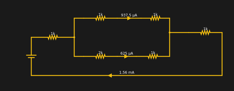
The current from the battery has to equal the current going into the battery. The two resistors at the extreme left and right have the same current through them (1.56 mA). Within rounding error of the simulator, each branch of the split has its share of the total (note the bottom leg has 3K total resistance and, thus, carries less current).
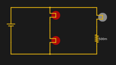
Kirchhoff’s voltage law (KVL) says that the voltage around a loop has to sum to zero. Take a simple example. A 12V battery has a 12V light bulb across it. How much voltage is across the bulb? 12V. If there are two identical bulbs they will still see 12V across each bulb.
You can simulate this circuit to see the effect. The loop with the two bulbs has 12V across it and each bulb gets half because they are identical. The right-hand path has different voltages but they still have to add up to 12.
All by itself, KVL wouldn’t be very useful, but there is a principle known as superposition. That’s a fancy way of saying that you can break a complex circuit up into pieces and look at each piece, then add the results back and get the right answer.
Analysis
You can use these two laws to analyze circuits using nodal analysis (for KCL) or mesh analysis for KVL, regardless of how complex they are. The only problem is that you wind up with lots of equations and may have to solve them as a system of simultaneous equations. Luckily, computers are really good at that, and circuit analysis software often uses one of these techniques to find answers.
Consider this circuit:
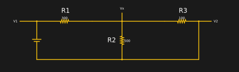
This is actually too simple since we know V1 and V2 right out of the gate (5V for the battery and 0, because V2 is connected to ground). In addition, a human would know to calculate the equivalent of R2 and R3, but that might not be apparent in a more complex circuit, especially to a computer.
The node labeled Vx has three currents. I1 is the current through the battery and R1 flowing in. I2 is the current flowing through R2 and I3 is the current flowing through R3. You can write equations for all three currents, easily:
I1=(Vx-V1)/R1

I2=(Vx-V2)/R2

I3=(Vx-V2)/R3
Of course, we know the values of everything on the right except Vx, so:
I1=(Vx-5)/300

I2=Vx/R2

I3=Vx/R3
Note that the first line above is “backward” because I1 is flowing into node Vx and the others are flowing out; there are several ways you could elect to handle this. Now using KCL we know that: I1+I2+I3=0 You can replace all of the I’s with their equation:
(Vx-5)/300 + Vx/500 + Vx/100 = 0

(5Vx+3Vx+15Vx)/1500 = 5/300

23Vx/1500=5/300

23Vx=1500(5/300)

Vx=25/23=1.09V (about)
For line 2 above, the least common multiple of 300, 500, and 100 is 1500 and we add 5/300 to both sides to get the Vx terms alone. In line 4 we multiply both sides by 1500 to arrive at the solution.
If you look at the simulation, you will see that Vx is 1.09V. Now you can go back in the equations and get I1, I2, and I3, by just plugging in values. Of course, real problems get thornier and usually wind up with a system of equations you have to solve.
If you really want to pursue the higher math, you might enjoy the Khan Academy video on nodal analysis, below. Note that they handle the idea of negative current explicitly. If you want to use their math on our example, then I2 and I3 are explicitly negative and I1 is derived from 5-Vx instead of Vx-5. Then you wind up with -23Vx=-25 and get the same result in the end. That’s how math is.
The other way to do this sort of systematic analysis with KCL and KVL is mesh analysis. There you use superposition and simultaneous equations. But don’t worry — it isn’t as hard as it might sound. Rather than go into that, you can watch another Khan Academy video on the subject. Just dust off those algebra skills.
History
[Gustav Kirchhoff] was a German physicist who worked all this out in 1845, about 20 years after [Ohm] worked out his law. Actually, [Ohm] wasn’t first, he was just the first to talk about it. [Henry Cavendish] figured out Ohm’s law in 1781 using Leyden jars (big capacitors) and his own body as an ammeter. He’d complete the circuit with his body and judge the current flow by the amount of shock he received. Now that’s dedication. [Ohm] had a better experimental setup and — as far as we know — didn’t shock himself as a matter of course.
You might think that [Ohm] was well respected for his discovery, but that wasn’t the case. The establishment was very upset with his findings. One German yearbook of scientific critique labeled it “a web of naked fancies.” The German Minister of Education called it a “heresy.” It was in opposition to Barlow’s law (suggested in 1825 by [Peter Barlow]) which said that current was related to the diameter of the wire and the length of it.
Actually, [Barlow] wasn’t totally wrong. He used a constant voltage and did not understand (as [Ohm] did) that the voltage source had an internal resistance. [Ohm], in fact, switched from batteries to thermocouples because at the time they had a more stable output and predictable low internal resistance.
It is hard to imagine today, but there was a lot of experimentation and law writing back then — not all of it correct, obviously. Often the person we associate with the work wasn’t really the first, just the one that published. Another example is the Wheatstone bridge. [Sir Charles Wheatstone] made it famous, but it was actually the brainchild of [Samuel Christie].
And?
For some reason, everyone knows Ohm’s law, but you don’t hear much about poor old [Gustav]. If you take an electrical engineering class, these laws are among the first things you learn. You might not use it every day, especially in this day of computer simulations. However, understanding analysis like this can help you develop an intuitive understanding of electronics.
By the way, the simulations in this post are using the Falstad simulator we’ve covered before. While it is common to use a simulator to just give you answers, it is also useful to let it check your work. The equations above, for example, would be easy to mix up signs or make another mistake. If the answer doesn’t match the simulator, you probably made a mistake. Sure, you can just read the value off the simulator, but that doesn’t let you develop the intuition that working through the math will.


Uh, no… the law of nodes is conservation of charge, not of energy.
I stop reading after this, sadly.
Wouldn’t charge not being conserved violate the convservation of energy though? The statement seems technically correct to me. Also this is the first tutorial I’ve seen on hackaday that teaches real circuit solving skills to beginners.
Charge conservation and mass-energy conservation are not the same, though, in teaching, I present the current law as conservation of mass-energy, as the charge carriers are conserved, and, in this case, being equivalent to conservation of charge.
KVL is conservation of energy. KCL is conservation of charge. I just took the simple road and was using energy in the generic sense because I didn’t want to go down that detour. If folks are interested, look up Noether’s theorem. Regardless, the main point was K’s laws makes sense in context of conservation.
This is one of the amazing things about the Internet. When I was in school, no one I knew had heard of or at least taught anything about Noether’s Theorem. A friend of mine who was at Stanford and had Leonard Schiff as his thesis advisor, ran across it by accident while researching something in the library.
Now, this very important theorem is frequently referenced, and this recognition I think drives more interest in the meaning of symmetries and deeper study of physics. The ability to leave a link tot he Wiki page or some other source instead of searching through am massive library – probably idiotically organized in Dewey Decimal – is huge.
We should keep some of the big libraries for reality shows in which contestants raised in the digital age race to find a quote in a book.
Simplest is not best. Noether’s Theorem results in charge conservation from the gauge invariance of the system, whereas energy conservation comes from the homogeneity in time.
Uh, there’s no need to bring homo into the equation…
And this is how a GFI works. If the current in does not equal the current out then there is an imbalance in the circuit (current is flowing elsewhere) and the circuit needs to turn off.
Yes, but when does the current equal?
Remember that reactive loads exist.
And that’s when I start swearing, because the freezer is off thanks to the outlet.
To fix this you either should install a snubber in line with the freezer or replace the outlet with one which has a modern GFCI. There’s no reason these days for a GFCI to nuisance trip on a household appliance, and many countries don’t even give exceptions in the electrical code to devices like fridges anymore.
The problem with reactive loads and GFCIs is that when you have lots of them in the house – all the CFL bulbs, computers, fridges, microwave ovens… barely anything is plain resistive anymore except the hob – it’s like the rogue wave effect: difficult to observe, but known to happen. Every now and then the stars align and your interrupter shuts your fridge down.
I live in such a country, the Netherlands.
As long as the hardware has proper insulation and not too many ground filters (as in L-||-E-||-N) there are no problems at all.
For example, in the Netherlands you are not allowed to have more than 4 separate circuits on one GFI, that is a GFI with 30mA tripping current.
I run a lot of IT gear, we run a washing machine, dryer, multiple fridges and a freezer, lots of switchmode power supplies, even some old school metal fluo. lighting fixtures and only had the GFI trip when:
– There actually was a ground fault
– When lightning struck (indirectly causing a ground fault)
As long as the GFI works like it should and the hardware is OK, nothing should happen.
Refrigerators and freezers are allowed to be on non-GFCI circuits for this reason. I may misremember, but I think a kitchen refrigerator is required to NOT have a GFCI. (USA national electrical code, other countries probably vary)
Reactive loads don’t make current “unequal” whatever the hell that was supposed to mean.
Reactive loads like non-PFC SMPS and others like cheap LED/CFL bulbs may send current through the ground wire during normal operation and cause a disrepancy between line and neutral.
Partially because of this, there exists some amount of noise for the GFCIs to deal with and they cannot be set low and sensitive enough to protect you from potentially lethal shocks without causing them to trip all the time. Hence their main point is to prevent electrical fires from happening by partial short circuits to the ground, and you may hope that your heart restarts itself after recieving a short 60+ mA shock.
That’s got nothing to do with them being reactive, but rather because of leakage through capacitors, or parasitic coupling to earth, and/or high frequencies. Motors are the textbook example of a reactive load, and will run quite happily without tripping earth leakage protection.
GFCIs (RCDs) in domestic applications aren’t required for stopping fires, they are for saving people from electrical shocks. Plain old thermal/magnetic circuit breakers are generally sufficient for fire prevention…
And RCDs are supposedly able to prevent lethal shocks by tripping quickly enough that your heart hasn’t yet gotten messed up. Here they are set at 30mA and trip in some tens of milliseconds, apparently fibrillation doesn’t occur until some hundreds of milliseconds, but I’m not going to test it.
>” but rather because of leakage through capacitors
And what are those if not reactive?
It’s pretty hard to get a ground leak from a correctly functioning resistive element such as a lighbulb or a space heater, whereas reactive loads with lots of capacitors in them often have ground currents due to normal operation.
More specifically, the problem with reactive loads is this:
http://ecmweb.com/content/beware-simplistic-fault-current-calculations
>”The ratio of reactance to resistance, or X/R, determines the peak asymmetric fault current. The total asymmetric current is a measure of the total DC component and the symmetrical component. The DC component causes the short circuit current to be asymmetrical. The asymmetrical component decays with time and will cause the first cycle of a fault current to be larger in magnitude than the steady-state fault current.”
Now suppose you have a reactive and ACTIVE load that keeps switching its inputs, so the X/R ratio changes all the time. That modulates the current that the GFCI sees, and may cause it to trip erroneously, or not trip for a moment with a real fault.
Ventricular Fibrillation occurs when you have a Q on T event. That is the Q wave (which is usually the start of the electrical signal for your heart to contract) occurs simultaneously with the T wave which represents the repolarization of the heart. In the case of electrocution causing V-Fib the stray current would represent the Q wave. So no matter how vanishingly short the time frame is for the GFI to trip there should still be a change that it occurs during the T wave.
This phenomena is also seen when a baseball player gets hit by a ball on the chest during the T wave. The heart is like a piezoelectric device it will generate an electrical impulse when hit thus causing a poorly timed Q wave resulting in V-Fib.
I myself have gotten a patient out of V-Fib using a precordial thump – said to generate about 0.6 joules of energy. (defibrillators typically run from 100-360 joules)
I think they do.
Consider an empty capacitor connected up to a D.C. supply. The inrush current charging the cap will definitely not be a balanced current – the current will go into the cap and not leave.
Now at some *later* time, the cap will let that current out, but a naive GFI has a short attention span.
A capacitor isn’t like a bucket that fills up. Charging it requires symmetric current through both wires.
Technically a capacitor is equally charged in all states.
One of my hackaday projects runs afoul of this concept: https://hackaday.io/project/4818-a-quick-220-clone .
The assumption of a GFI is that there’s no way that the current could be going somewhere *else* unless there was a ground fault. Here in the U.S. with split phase power, that’s not *necessarily* true…
How so? GFCI is measuring between hot and neutral in a single phase circuit. If a split phase GFCI measures it between both hots and neutral, all currents still sum to zero when there is no fault.
You misunderstand what that project achieves. It takes two individual single-phase 120v circuits and combines them to make a single split-phase 240v circuit. The problem happens when one attempts to use a 120v circuit protected by a 120v GFI. The current leaves the hot line and returns via a different hot line and that GFI immediately trips.
The assumption also fails when you have devices which may couple to other things, such as your AV set sending or reciving current to some other device, or coupling to ground via filter capacitors, or there’s a temporary DC offset in the wiring which superimposes a current to the AC…
I don’t know about “respect”, but one really needs to understand KVL/KCL and Ohms in order to make any progress in being an EE.
In many cases.. no, actually not. (EE myself)
I would agree conditionally. You need to know it to make progress in going through EE classes. I have had jobs where I used this every day. And I have had jobs where I would never use this. But I still think understanding things like this develops intuition about circuits that you ought to have.
Worst example of this was my boss at an unnamed company. I had a test rig down on an IC die where I had a fixed voltage going through some microprobes and I was measuring the current. We were looking for contamination that would show up as a resistance. My boss at the time had a BS in something strange and an MSEE and clearly did not have any real intuition about real circuits. He insisted that I needed an ohm meter (actually, for some reason, he called it a “registrance meter”) and proceeded to rewire my TM500 rack (shows you how long it has been) to include an ohmmeter.
I agree. In the first big circuits book in EE courses, Ohms law gets a little attention, followed by loads and loads of DC KVL/KCL and constructing and solving systems of linear equations. Then AC is introduced and they are linear systems with complex algebra. (Are Irwin or Floyd still used?)
People using the wrong words for things always makes me think they are stupid.
I once worked with a person getting paid a lot more money than me who used to go on about arduinos… except that he’d always refer to them as “andrinos”
sigh.
I have heard that pronounced that way more than once. Don’t know why.
There are exceptions, I work with several colleagues who are not native English speakers and it’s a running joke about them not being able to pronounce “accelerometer”. So now the everyone in the lab lovingly refers to them as “g meters”
I still fumble the word “arduino” off and on, because I saw them mentioned for a long time before ever using one, and the letters are somewhat similar to “android”. Then once I played with some, I did so for well over a year before having any reason to say it out loud. Also have a touch of dyslexia, so it wouldn’t have taken a lot have it semi-permanently wrong. That, along with being a non-native English speaker who speaks almost nothing but English, had a paradoxical opposite effect though – I’m kind of self conscious about mispronouncing/misspelling things quite a bit, so if it’s something that comes up a lot I try to practice (in private) to correct it or at least mitigate it some.
How did you get your EE degree? If you don’t understand KVL/KCL I find it hard that you would have passed ELEC101. You may not ever *use* it, but you need to understand it to make progress towards becoming an EE :-)
Catch questions in the exams is the usual answer. It’s generally considered cheating, but many professors leave them in because some of the 101 courses are shared with things like mechanical engineering where you have to pass a number of courses in other disciplines that you typically never need.
Basically, it’s possible to solve some of the problems without understanding KVL/KCL either by rote memory or by winging it without realizing what you’re doing. Then later on it is assumed you already know the stuff, and you get to use circuit simulators.
Same with ‘College Physics”, the non-calculus course. For example, required for all pre-meds, and used to weed them out. The physics profs don’t like being used as the axe and amazingly, everyone in the class gets good enough grades to go forward.
Analysis of op amp circuits builds on these laws.
Kirchhoff did far more. Much of seismic imaging is done using Kirchhoff’s method which sums all the diffractions in a wavefield to recover an image of the scatterer. It does the equivalent of a hologram in situations in which you can record both amplitude and phase of the wavefield. Many megawatts of power are consumed every day running Kirchhoff migrations on huge (50,000 core) clusters.
BTW Kirchhoff is the cheap solution. The current fancy method is reverse time migration which is probably 2-3 orders of magnitude more expensive. Kirchhoff is ray based whereas RTM is wave based.
I’ve got a high school physics exam on this in four days. This article couldn’t have come at a better time.
Changing values in the simulator will give you an endless number of problems you can solve and then use the sim to get the solutions. Good luck!
“The current going into the resistor better be the same as the current going out of it and into the LED.”
Doesn’t the resistor generate a very, very small amount of heat? Surely that consumes some of the current.
Nope. Current is electrons per second. If you are converting electrons to heat, you probably have a Nobel prize coming. Or your lab will be a smoking crater. One or the other.
Using the really bad and misleading “water flow” analogy for electrical current: The resistor is a constriction in the pipe, the friction of the flow produces vibration and heat, but all the water that goes in comes back out, just slower than it would if there was no constriction. Note that it goes in at the same speed it comes out.
The power dissipated by the resistor as heat is equal to current through times voltage across. In a sense (and I am sure I will be righteously flamed for this, because it’s more complex than this), the heat comes from the voltage drop. No current is consumed by the heat, but voltage is consumed by the heat. If you have a perfect conductor, zero resistance, it consumes no power and produces no heat.
I’m sure someone else will spend a few minutes and write up a better explanation. Or just post a link to one.
Current is coloumb per second.
You are right, of course, but I was trying to keep it simple. And the official definition of a Coulomb is “a double mega butt-load of electrons having a beer bash on a beach.”
Nope. That heat generated consumes part of the voltage (causing the voltage drop across the resistor), but the current will always be the same at all points in a loop of a circuit.
When current goes through a resistor, you can also get rather large amounts of heat generated. All heating elements are just resistors at their core.
I would rephrase KCL as “The sum of all current’s going into a node will always be zero” — rather than “the sum of the current going in and the current going out will always be zero” because it only has a negative sign if you’re defining positive as going in
A Kirchhoff descendant, Jay Kirchhoff, was a senior engineer at Broadcom in Atlanta. I met him around 2000 during a cable modem development project. He eventually rose to Vice President of Marketing. Great guy, both extremely sharp and very personable.
I’ve been amazed at the number of EEs and BSEEs I’ve known that don’t know KCL/KVL.
It seems like such a basic thing. How can you not know them and be working in electronics?
Thanks For OHM or khichoffs rule