Lord Kelvin’s name comes up anytime you start looking at the history of science and technology. In addition to working on transatlantic cables and thermodynamics, he also built an early computing device to predict tides. Kelvin, whose real name was William Thomson, became interested in tides in a roundabout way, as explained in a recent IEEE Spectrum article.
He’d made plenty of money on his patents related to the telegraph cable, but his wife died, so he decided to buy a yacht, the Lalla Rookh. He used it as a summer home. If you live on a boat, the tides are an important part of your day.
Today, you could just ask your favorite search engine or AI about the tides, but in 1870, that wasn’t possible. Also, in a day when sea power made or broke empires, tide charts were often top secret. Not that the tides were a total mystery. Newton explained what was happening back in 1687. Laplace realized they were tied to oscillations almost a century later. Thomson made a machine that could do the math Laplace envisioned.
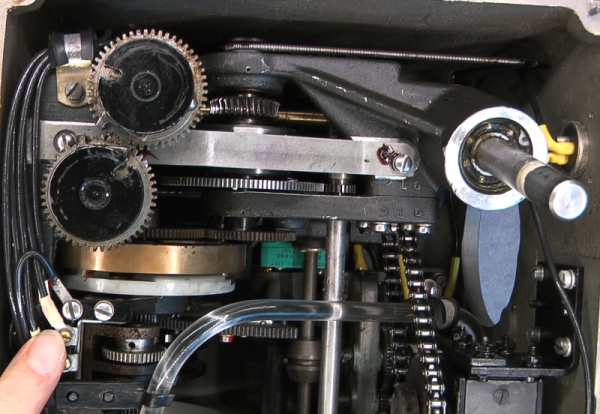
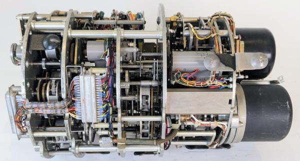
We know today that the tides depend on hundreds of different motions, but many of them have relatively insignificant contributions, and we only track 37 of them, according to the post. Kelvin’s machine — an intricate mesh of gears and cranks — tracked only 10 components.
In operation, the user turned a crank, and a pen traced a curve on a roll of paper. A small mark showed the hour with a special mark for noon. You could process a year’s worth of tides in about 4 hours. While Kelvin received credit for the machine’s creation, he acknowledged the help of many others in his paper, from craftsmen to his brother.
We actually did a deep dive into tides, including Kelvin’s machine, a few years ago. He shows up a number of times in our posts.