As [Sam Ben-Yaakov] points out in a recent video, you don’t often see flyback converters these days. That’s because there are smarter ways to get the same effect, which is to convert between two voltages. If you work on old gear, you’ll see plenty of these, and going through the analysis is educational, even if you’ll never actually work with the circuit. That’s what the video below shows: [Sam’s] analysis of why this circuit works.
The circuit in question uses a bridge rectifier to get a high-voltage DC voltage directly from the wall. Of course, you could just use a transformer to convert the AC to a lower AC voltage first, but then you probably need a regulator afterwards to get a stable voltage.
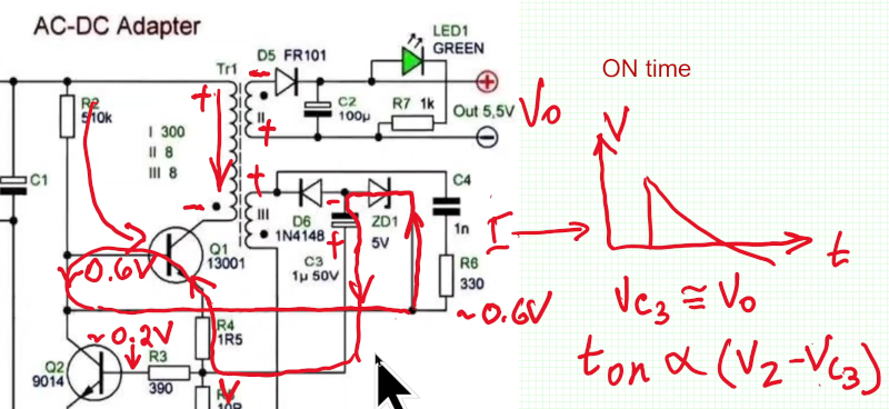
The converter operates as an oscillator. The duty cycle of the oscillator varies depending on the difference between the output voltage and a zener diode reference. These circuits are often difficult to model in a simulator, but [Ben] shows an LTSpice simulation that did take a few tweaks.
As he mentions, today you’d get a switching regulator on a chip and be done with it. But it is still interesting to understand how the design works. Another common flyback circuit used an oscillator driving a CRT for the primary, more or less. If you want to learn more, we can help with that, too.


Ahh yes the fuzzy feeling on your fingers because flyback wall wart manufacturers are allergic to small good quality class Y caps and low making transformers with enough leakage inductance it can probably power another couple of windings
Well, the leakage inductance is in fact the operating principle of the flyback “transformer”, which is not a transformer per se, but two (or more) magnetically coupled inductors.
**Magnetically coupled inductors with an air gap
The sentence “you don’t often see flyback converters these days” is an utter nonsense. Literary every non-isolated low power dc/dc converter is a flyback converter.
Yes, it only really makes sense with the added “self-oscillating”, which is only evident from looking at the Video-Thumbnail and not mentioned anywhere in the article.
And regarding “you could just use a transformer to convert the AC to a lower AC voltage first”: that would really defeat the sense of using a SMPS in the first place.
Exactly. On the flip side, I’ve designed several self-oscillating offline flyback SMPS circuits with just three transistors—plus a secondary TRIAC crowbar for robust protection—and I find the process of refining them into solid, reliable designs to be a genuinely rewarding mental exercise.
I miss those days a bit.
No tubes? I would expect that from a circuit that uses AC directly.
I could do that
As a radio tech from the CRT eara, flyback was the word, the horizontal deflection transformer was a can of flyback worms, some extremely clever engineering was put into these, check out som of the old circuit diagrams to be amazed…
But weren’t the IC based circuits from the 70s sort of an improvement?
I know that most b/w portable TVs (AC and 12v input) with ICs and internal DC power supplies still work to this day.
As far as I know, the line end transformers were cheaply made and not seldomly failed because
the overly thin wires would melt if the transformer got hot due to misaligment (video signal with illegal timings).