Electricity flow is generally invisible, silent, and not something that most humans want to touch, so understanding how charge moves around can be fairly unintuitive at first. There are plenty of analogies to help understand its behavior, such as imagining a circuit as a pipe of water, with pressure standing in for voltage and flow standing in for current. But you can flip this idea in reverse and use electric circuits to model other complex phenomena instead. [Oxx], for example, is using circuit theory to model his home’s heating systems.
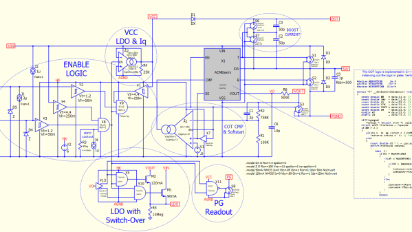
To build his model, he’s using LTSpice, a free circuit simulation program. Using voltage to model temperature and current to model heat flow, he’s set up a model for his home to compare the behavior of a heat pump and a propane furnace. A switch model already in LTSpice with built-in hysteresis takes the place of the thermostat. Using temperature data for a single day in January [Oxx] can see how each of his two heating systems might behave, and the model for the heat pump is incredibly close to how the heat pump behaved in real life.
The model includes all kinds of data about the system, including the coefficient of performance of the heat pump and its backup electric resistive heater, and the model is fairly accurate at predicting behavior. Of course, it takes a good bit of work to set up the parameters for all of the components since our homes and heating systems won’t be included in LTSpice by default, but it does show how powerful an electric circuit analog can be when building models of other systems. If you’ve never used this program before, we’ve featured a few guides to getting started that you can take a look at.
Thanks to [Jarvis] for the tip!
Continue reading “Modeling Home Heating Systems With Circuit Simulation Software” →