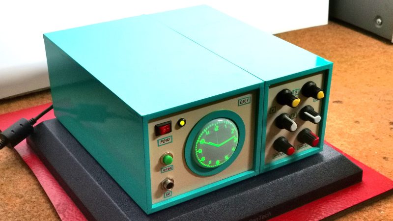
Superlatives are tricky things. [mircemk]’s guide “How to make Simplest ever Oscilloscope Clock” falls into that category. It’s that word, simplest. Certainly, this is an oscilloscope clock, and a nice one. But is it simple?
There’s a nice oscilloscope circuit with a cute 2″ 5LO38I CRT and EF80 tubes for horizontal and vertical deflection that we’d say is pretty simple. (It’s based on an earlier DIY oscilloscope project [mircemk] did.) The bill of materials is remarkably sparse– but it’s modules that do it. One entry is a DC-DC step up supply to get the needed HV. Another is a LM317 to get 6.3 V to heat the tubes. The modules make for a very simple BOM, but on another level, there’s quite a bit of complex engineering in those little modules.
When we get to the “clock” part of the oscilloscope clock, that quandary goes into overdrive. There’s only one line on the BOM, so that’s very simple. On the other hand, it’s an ESP32. Depending on your perspective, that’s not simple at all. It’s a microcomputer, or at least something that can play at emulating one.
Oh, in the ways that matter to a maker — parts count, time, and effort, this oscilloscope clock is very simple. The fact that its actually a vector display for a powerful little micro just adds to the versatility of the build. We absolutely love it, to be honest. Still, the idea that you can have millions of transistors in a simple project — never mind the “simplest ever” — well, it just seems weird on some level when you think about it.
It all comes back to what counts as “simple”. If we’re taking lines on a BOM, arguably this would be even simpler if you used an existing oscilloscope.


A 555 or even a single transistor is horribly complex in itself and a product of thousands of years of technological development.
I think a project is simple when the work done for that particular project is simple, no matter how giant shoulders it stands on.
This is just my simply posted comment.
Agree. We have those cool complex things precisely for the purpose of making our projects simpler. I could argue that the processes that give us multilayer printed circuit boards are pretty damn complex but nobody adds a qualifier to simple projects that use them.
It’s just Tyler, aka the approximate, inaccurate guy who is trying to possible text fester thanks the Aussie generator
Thousands?
Actually, single transistor is not that complicated. You can make one using crucible and manually adding P and N layers. Then such layered casting is allowed to cool and is cut into individual dies. That’s how Japanese started their electronics industry in 1950s.
Sure they won’t be as uniform as a roll of 2N2222s downloaded from Digikey or TME, but it will work.
nice project, but that schematic…. yikes!
it took ke a full 5 minutes to convert it in my head to something i understand.
may i suggest putting the input tubes to the left so the signal path is traversing from left to right on the schematic. then putting the +350v line on top would also help. now the tube. it has numbered pins, does it has corresponding signal input james as well? i think they are positioned from left to right as the electrons go from cathode to anode and beyond though the deflection plates, but that’s just a guess.
a clear ground line is also handy. look at the capacitor with the ef80 tubes. the ground can go directly to the ground line, in stead of the cluttering way through the cathode resistor. ps. no decoupling there?
just my 2 cents
“Simplest-ever o’scope clock build” is probably defensible…
Simply nice. Love it. My garage hides similar CRT too, beside some magic eye tubes. I am on the quest to dig it out and make it alive with some HV stuff. Carpe diem, tempus fugit.
“First I will focus on the signal generation part. It is extremely simple and uses only an ESP32 Microcontroller board without any external components”
Oh, so it’s just Tyler we have to scold for this.
“On the other hand, it’s an ESP32. Depending on your perspective, that’s not simple at all. It’s a microcomputer”
Sigh.
If you add a keyboard, external IO, including a display, maybe.. otherwise can we avoid confusing the microcontroller vs microcomputer categories? Thanks.
https://www.instructables.com/ESP32-Basic-PC-With-VGA-Output/ ?
Now the question is, how would you draw the clock face without a microprocessor?
Making a circle is fairly simple. You make a sin-cos oscillator and the dot goes around in a circle. This is two op-amps, some capacitors and resistors. You can then scale the voltage up or down to get a bigger or a smaller circle.
Then the hour lines: a short duty cycle square wave oscillator that beats 12 times for each revolution and switches a transistor. The transistor switches the scaling factor of the circle oscillator, resulting in radial lines or notches towards the center.
The clock hands can be drawn in a similar fashion using more oscillators and comparators etc. The output signal of all of these oscillators is then switched in and out, so we draw the clock dial, then hands, then dial… etc. repeatedly.
Not difficult in principle, but I wouldn’t want to tune all of that to run right.
Have a look at the technology in the original Tektronix 7D01 Digital Readout Plug-In
Here’s an interesting article from 1971 on using an oscilloscope as a multi-line character display terminal, using just TTL, a few op-amps and discrete parts. It pre-dates the TV Typewriter by a few years:
https://archive.org/details/bitsavers_ElectronicignV19N2319711111_83573468/page/n75/mode/2up
I would love to see someone recreate this as it was, NOT using a microprocessor (or even a 555).
The circular oscillator I described is a very basic version of the starburst character generator. As far as I can tell, they were shift registers or masked ROMs, and controlling them would require some sort of a microprocessor to dynamically address the patterns.
The article says ‘any D type flip flop can be used for the shift register and timing control circuits’. No ROMs at all. Yes a processor is required to run the interrupt-driven driver; they likely had a small minicomputer given the university setting and timeframe. But it is not drawing the vectors directly but just turning the appropriate stroke segments on and off.
I shouldn’t think you’d need more than a pretty simple state machine to address a ROM and issue the correct vectors in the correct sequence to draw a clock. No microprocessor needed.
http://cathodecorner.com/sc200theory.html used Lissajous to create the face and numbers (but it did have a processor). https://www.sgitheach.org.uk/scope4.html has no processor (only TTL logic) but displays the time as a 7-segment display on the CRT.
I’ve seen several variants of this available in kit form from a Chinese and Russian sellers. That is definitely not as cool as rolling your own and the build cited here is very nice. A kit would be a an easy way to get the display tube and socket. It looked like most of the ones I saw were using 1970s era Russian display tubes.
The biggest downside is the electrostatic deflection tubes ususally didn’t have a large beam deflection angle and hence had a fairly long neck versus a given screen size.
I’ve got an old Sony/Tektronix logic analyzer kicking around in my basement. If I recall, it had a 110 degree magnetic deflection tube with five inch screen for its raster display. It has a rather short neck. That might be able to be interestingly repurposed.
I’ve also got an MB Vectrex video game console kicking around. That’s curiously a magnetic deflection CRT, but a vector display. It is about a 12 inch almost 2:1 aspect portrait mode CRT. Back in the late 1980s I bought a dozen Vectrexes to use as waveform displays in a biology lab. We simply bypassed the 6809 CPU board and jumperd around the beam blanking so that we could draw on the screen more slowly. They actually worked out very nicely and they were only 39 bucks each at Children’s Palace.