The completed oscilloscope in parts, with the screen in the front connected with prototyping wires, protoboarded buttons on the right, and the BlackPill board somewhere behind

DIY STM32 Scope Is Simple, Cheap, And Featureful

Would you like to have a small digital oscilloscope? Do you have a spare BlackPill (STM32F401) board and a TFT display laying around? [tvvlad1234] presents us with a simple and educational digital storage oscilloscope design that barely needs any components for you to build one, and it’s packed with features just like you would expect from a self-respecting open-source project. Not just that — it can even stream data to your computer, in a format compatible with the TekScope software!

The same scope design, but now on a self-etched board
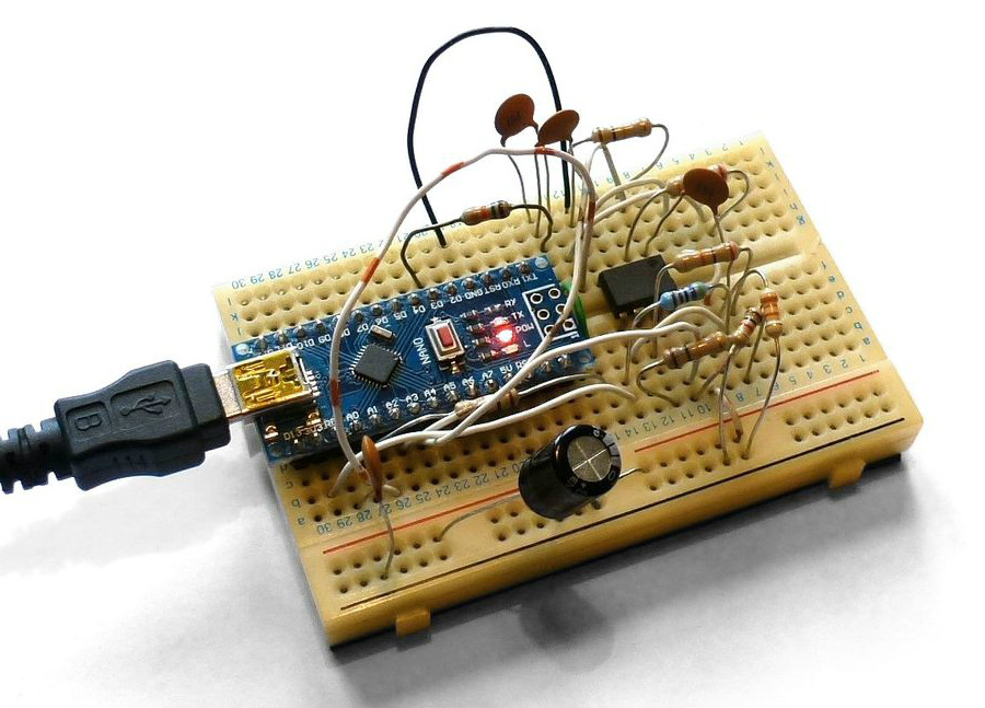
It’s hard to overshadow just how easy this scope is to build, use, and hack on. You really don’t need much in the way of parts, a protoboard will do, though you can also etch or order your own PCBs. The front-end is super straightforward to find components for and assemble, a few opamps and resistors is all you need. So after jumper-wiring the LCD and three push buttons to your BlackPill, you’re golden.

Of course, the simple frontend results in the input range being from -3.3 V to 3.3 V, but as you could guess, this is exactly the kind of project where you could tweak the resistors and even upgrade it later on. Are you a bit lost in how oscilloscopes work? [tvvlad1234] has an explainer for you, too!

This build could easily take up a honorary “temporary turned permanent” place on your bench, thanks to its McGyver-esque qualities. It’s also, quite possibly, a better scope than the red “soldering kit” ones we’ve seen online. All in all, it’s a strong contender in the “simple and powerful DIY scope” arena, before this, we’ve seen one built with an Arduino Nano, and one with a Pi Pico.

Building A Pocket Sized Arduino Oscilloscope

There’s little question that an oscilloscope is pretty much a must-have piece of equipment for the electronics hacker. It’s a critical piece of gear for reverse engineering devices and protocols, and luckily for us they’re as cheap as they’ve ever been. Even a fairly feature rich four channel scope such as the Rigol DS1054Z only costs about as much as a mid-range smartphone. But if that’s still a little too rich for your taste, and you’re willing to skimp on the features a bit, you can get a functional digital oscilloscope for little more than pocket change.

While there are a number of very cheap pocket digital storage oscilloscopes (DSOs) on the market, [Peter Balch] decided he’d rather spin up his own version using off-the-shelf components. Not only was it an excuse to deep dive on some interesting engineering challenges, but it ended up bringing the price even lower than turn-key models. Consisting of little more than an Arduino Nano and a OLED display, the cost comes out to less than $10 USD for a decent DSO that’s about the size of a matchbox.

But not a great one. [Peter] is very upfront about the limitations of this DIY pocket scope: it can’t hit very high sample rates, and the display isn’t really big enough to convey anything more than the basics. But if you’re doing some quick and dirty diagnostics in the field, that might be all you need. Especially since there’s a good chance you can build the thing out of parts from the junk bin.

Even if you’re not looking to build your own version of the Arduino-powered scope [Peter] describes, his write-up is still full of fascinating details and theory. He explains how his software approach is to disable all interrupts, and put the microcontroller into a tight polling loop to read data from the ADC as quickly as possible. It took some experimentation to find the proper prescaler value for the Atmega’s 16MHz clock, but in the end found he could get a usable (if somewhat noisy) output with a 1uS sample rate.

Unfortunately, the Arduino’s ADC leaves something to be desired in terms of input range. But with the addition of an LM358 dual op-amp, the Arduino scope gains some amplification so it can pick up signals down into the mV range. For completion’s sake, [Peter] included some useful features in the device’s firmware, such as a frequency counter, square wave signal source, and even a voltmeter. With the addition of a 3D printed case, this little gadget could be very handy to have in your mobile tool kit.

If you’d rather go the commercial route, Hackaday’s very own [Jenny List] has been reviewing a number of very affordable models such as the DSO Nano 3 and the JYE Tech DSO150 build-it-yourself kit.

[Thanks to BaldPower for the tip.]

A DIY Nine Channel Digital Scope

Have you ever found yourself in the need of a nine channel scope, when all you had was an FPGA evaluation board? Do not despair, [Miguel Angel] has you covered. While trying to make sense of the inner workings of a RAM controller core, he realized that he needed to capture a lot of signals in parallel and whipped up this 9-channel digital oscilloscope.

The scope is remote-controlled via a JavaScript application, and over Ethernet. Graphical output is provided as a VGA signal at full HD, so it is easy to see what is going on. Downloading sampled data to the controlling computer for analysis is in the works. [Miguel] runs his implementation on an Arty A7 development board which is currently available for around a hundred dollars, but the design is transferable to other platforms. The code and some documentation is available on GitHub and there is a demo video after the break.

Continue reading “A DIY Nine Channel Digital Scope”

Hybrid Raspberry Pi + PIC32 = Oscilloscope And Function Generator

The PicBerry is a student final project by [Advitya], [Jeff], and [Danna] that takes a hybrid approach to creating a portable (and affordable) combination digital oscilloscope and function generator. It’s based on the Raspberry Pi, features an intuitive Python GUI, and can generate and measure simultaneously.

But wait! The Raspberry Pi is a capable little Linux machine, but meeting real-time deadlines isn’t its strong suit. That’s where the hybrid approach comes in. The Pi takes care of the user interface and other goodies, and a PIC32 over SPI is used for 1 MHz sampling and running a DAC at 500 kHz. The idea of combining them into PicBerry is to get the best of both worlds, with the Pi and PIC32 each doing what they are best at. The readings are sent in batches from the PIC32 to the Pi, where the plot is updated every 30 ms so that user does not perceive any visible lag.

The project documentation notes that improvements can be made, the speeds are a far cry from regular bench equipment, and the software lacks some typical features such as triggering, but overall not bad at all for under $50 of parts. In fact, there are hardly any components at all beyond the Raspberry Pi, the PIC32, and a MCP4822 digital-to-analog converter. A short demo video is embedded below.

Continue reading “Hybrid Raspberry Pi + PIC32 = Oscilloscope And Function Generator”

Hackaday Prize Entry: ESP Swiss Knife

The best equipment won’t help you if you don’t have it with you in the moment you need it. Knowledge, experience, and a thick skin may help you out there in the mud of the hardware battlegrounds, but they can’t replace a multimeter, an oscilloscope, a logic analyzer, a serial console or a WiFi access point. [Arcadia Labs] has taken on the challenge of combining most of these functions into a single device, developing the Hacker’s equivalent of a Swiss Army Knife: The ESP Swiss Knife.

esp_swiss_knife_enclosureJust like a Swiss Army Knife is first and foremost a knife, the EPS Swiss Knife is first and foremost an ESP8266. That means it is already a great platform for any kind of project, and [Arcadia Labs] supercharged the plain ESP-12E module by adding a couple of useful features commonly used in many projects. There’s an OLED display, four pushbuttons, a temperature sensor, and a Li-Ion cell with a charging module to power the device on the go. A universal “utility socket” breaks out the ESP8266’s leftover GPIOs and the supply voltage for attaching further peripherals.

With the hardware up and running, [Arcadia Labs] went on with building a couple of applications to provide the functionality that would make the device earn its name. Among them is a basic oscilloscope, a digital NTP based clock, a thermometer, a WiFi tester, a weather station and a 3D printer status monitor. More applications are planned, such as a chronometer, a timer, a DSLR intervalometer and more. A protective 3D printable enclosure is also in the works. [Arcadia Labs] has been joining the Hackaday Prize 2014 and 2015 before and we’re glad to see another great build coming into existence!

The HackadayPrize2016 is Sponsored by:

One Dollar USB Sound Card Turned O-Scope

Using the inputs on a computer’s sound card is an old trick to fake a very simplistic, AC coupled, slow oscilloscope. You can get DC operation by desoldering a couple capacitors, but if the sound card is integrated into the motherboard it raises the stakes if you mess that up.

[TMSZ] has a better option, a ~1 dollar USB sound card which is easily hacked to work as a simple oscilloscope. Easily found on eBay, the 7.1 virtual channel sound card is identical in brains to a more expensive c-media model, but the layout of the PCB makes it easier to bypass the DC blocking caps. Software and DLL files to use the sound card with Miniscope v4 — a Windows GUI for oscilloscopes — are also linked, so getting set up should be fairly simple.

Now of course this is not lab-grade measurement equipment: the sampling rate is limited to 44KHz and the voltages must be in the typical “line level” range, under two volts. If you don’t mind a little extra noise, you can increase the input impedance with a single resistor. This extends the input range up to six volts, which covers most hobby and microcontroller usage.

So if you’re really in need of a scope, but only have a buck to spend, this may be just the hack for you! Those willing to shell out a hefty sum for a high-end headless oscilloscope should look onto the virtual bench.

Homebrew Analog Scope Project Log

[GK] had some old CRTs lying around, so naturally he decided to build an old school analog scope with one of them. Lucky for us, he’s been documenting his progress. Since it was a big project to tackle, he started out with Spice modeling to work out all the right values.

Prototyping the power supply took some custom transformer winding, but when done, the power supply did the job. Although he’s still wiring up the Z (intensity) axis, the scope is already capable of displaying signals and even text characters using a character generator he built earlier (see video below).

[GK] spends most of the time so far talking about the high voltage power supply design. For the particular tubes he had on hand he needed +200V, -400V, -550V, and 6.3VAC for the CRT heater. This is certainly not the typical Arduino-based digital scope that everyone builds at least once.

We love analog scopes for art projects, logic analyzer conversions, and gaming. Of course, if you don’t have an old CRT in your parts bin, you might consider trying a laser.

Continue reading “Homebrew Analog Scope Project Log”