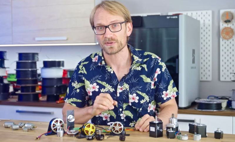
It’s little secret that stepper motors are everywhere in FDM 3D printers, but there’s no real reason why you cannot take another type of DC motor like a brushless DC (BLDC) motor and use that instead. Interestingly, some printer manufacturers are now using BLDCs for places where the reduction in weight matters, such as in the tool head or extruder, but if a BLDC can be ‘stepped’ much like any stepper motor, then why prefer one over the other? This is the topic of a recent video by [Thomas Sanladerer], with the answer being mostly about cost, and ‘good enough’ solutions.
The referenced driving method of field-oriented control (FOC), which also goes by the name of vector control, is a VFD control method in which the controller can fairly precisely keep position much like a stepper motor, but without the relatively complex construction of a stepper motor. Another advantage is that FOC tends to use less power than alternatives.
Using a FOC controller with a BLDC is demonstrated in the video, which also covers the closed-loop nature of such a configuration, whereas a stepper motor is generally driven in an open-loop fashion. Ultimately the answer at this point is that while stepper motors are ‘good enough’ for tasks where their relatively large size and weight aren’t real issues, as BLDCs with FOC or similar becomes more economical, we may see things change there.


I’m surprised we haven’t seen brushed DC motors with position feedback like in consumer inkjet printers. Even with a dozen nylon gears, I would still expect it to be far cheaper than heavy steppers with drivers.
With brushed DC motors you can’t lock them by driving at specific current and voltage. You can do that with BLDC and especially with steppers. The one problem with steppers is that the holding torque drops with microstepping. At 1/16 steps you get 9.80% of nominal torque, and that drops to 4.91% with 32 microsteps. With 3D printing that’s not a big deal as the moving mass is quite small. But for CNC machines in which a spindle alone weights twice as much as even the heaviest extruder head, this creates a problem of loosing position. And once you loose a few steps, your work is ruined, and you can even break the milling bit because machine doesn’t know where it is and thus it can hit the part holder (which happened to me a few times).
That is why a brushed DC motor with position feedback comes in. You’re right, in itself the motor can’t be “locked in place”, but using a position control loop, this is perfectly possible, even without consuming current when it is not battling forces to stay in position (a stepper always consumes). It basically behaves like a hobby servo motor then.
And like a hobby servo, it has some compromises like dead band and loop response time.
A stepper motor in open loop control is fire and forget. Either it has enough torque/power/speed to perform the movement, or it doesn’t. Having the feedback loop doesn’t help the motor break physics.
A stepper can for a short time have more torque, just increase the voltage. Closed loop can do that when it’s needed, open loop has no concept of need and is limited by worst case thermals to have lower achievable torque.
The feedback loop still has to respond to the need of torque by recognizing that the motor is lagging behind where it’s supposed to be, but that’s damage already done if you’re driving two motors at the same time and they have to remain in sync.
So the open loop stepper either does the motion you demand of it, or not. The feedback controlled BLDC motor does the motion if it can, and if it fails it’s too late to correct because it’s already made a beeline to the wrong position. It can get back on track, but when you’re operating that close to the limits to need corrective action, it’s going to be veering off all over the place and the result won’t be acceptable.
The closed loop feedback is useful in fine positioning assuming you don’t have high torque/speed demands at the same time. It eliminates the non-linearities of microstepping and cumulative errors caused by missed steps, but it won’t push the motor past its fundamental performance limits in a helpful way. If your motor is too small, it is too small.
Which is another way of saying: you can’t compensate for bad mechanical design in software.
The alternative and often better way to do it is to pre-empt the need for high torque by recognizing that you’re going to be demanding high acceleration and increasing the drive voltage before you run off track, then reducing it back down when you’re not demanding as much. That implies you have a dynamic model of the system to predict when and how much torque you will be needing before you actually need it.
Then you can use feedback control on top to correct for the discrepancies between your model and the actual hardware.
In the end it’s a question, how big a motor should be or how precise the movement must be. With 200 steps motor and 4mm pitch screw and no microstepping I get 0,02mm resolution. Adding half-steps is enough to get 0,01mm resolution, something my current 3D printer has with its core X-Y setup. And I retain more than 70% of the nominal torque. The movement of my CNC mill is a bit jerky, but it’s less likely to loose position during operation. I had a machine that was set for 800 steps per rotation, and it couldn’t really operate because it lost position too easily with its small and underpowered motors. Switched to 400 steps, adjusted currents and changed power supply to higher voltage, and it started to work decently, despite being a cheap 3018 mill with worst spindle ever, and many (poorly) 3D printed parts…
First order approximation of a stalled brushed DC motor is a dead short.
They can hold a fixed position, but don’t like it.
Also: Don’t anthropomorphize components, they hate that.
No, .holding torque does not drop with microstepping. That is a widespread and stubborn misconception. The only thing that microstepping does is approach the motor currents with an ever more accurate sinusoidal waveforms.
The original article (somewhere from the ’60-ies I think) was that if you wan to reach the accuracy of x fold microstepping, then you can not apply more torque to the motor (Assuming no feedback). Depending upon the applied torque, there is going to be a phase shift between the electrical and mechanical magnetic fields in the stepper motor. That is all. Read up a bit on FOC, where the goal is to maintain a 90 degree phase shift between the electrical and mechanical electric fields to optimize motor efficiency.
Or to write it another way: The difference between 1/8 1/16 or 1/64 microstepping is only tiny differences in the motor current, but according to that old article it would have a giant effect on motor torque.
The reason geared DC motors are not common is that you can’t have the backlash of the gears in a 3D printer. Once you add higher quality gears and the position feedback, it’s going to be more expensive then a simple stepper motor.
Care to share the data that corroborates that?
So the “torque loss” is about how much torque can be applied against a holding motor before the rotor deviates by the microstep angle.
FOC is actually about the vector sum of two fields: the rotor field and the torque producing field which are at right angles. What comes out of the sum isn’t necessarily at 90 degrees all the time. Full FOC can do both orientations at once, which is the case with induction motors where you need to excite the rotor with something. With PMSM (BLDC) motors you might apply a field for or against the magnets and alter the Kv constant of the motor on the fly for more torque or more speed. The resulting sum will not be at 90 degrees.
But yes, a simple BLDC controller will just attempt to shift the magnetic field 90 degrees ahead of where the rotor is pointing, and will continue to accelerate until the motor runs out of torque and can’t speed up any more.
The problem is backlash. Inkjet printers only need to move in one direction until it’s time to zip back across and start the next line. 3D printers are constantly changing direction so you’d have to use software backlash compensation, but that requires tuning, and causes a small time delay during the backlash take-up move which would show up in the print.
not really.
inkjet printers use an absolute linear encoder ..open the lid and you’ll see a thin transparent band with tiny vertical bars along its entire length. this is the encoder and any backlash or overshoot is compensated by the printer with no calibration required.
printers have incredibly good accuracy especially considering their price, and the wild speeds they can handle. and they’re also super quiet.
The linear encoder is used to time the dropping of ink, as that can be extremely precise controlled. Even if the motor is a bit slower/faster, the linear encoder ensures that drops drop when they should drop.
With 3D printing, life isn’t that simple, extrusion doesn’t start/stop on a whim.
i agree that backlash is why we don’t see more gears in 3d printers. And i agree that it’s hard to compensate for. But once compensated for, i don’t think it has any real disadvantage. That’s just one of the cool things about computer control that i think is often under-appreciated. In antiquity, the mechanical defect had an unavoidable consequence. But with suitable computer control (e.g., in audio, “DSP”), some defects can actually genuinely be compensated for and then it isn’t a factor anymore. It does have a cost in some % of overhead — reduced speed or torque or what-have-you, but within those limits, compensation really works.
The fun part comes when you use precision rotary encoders to accurately microstep stepper motors…
no HaD search results for S42B so far.. not quite precision encodee, but good-enough?
https://youtube.com/watch?v=eM8zSG8fEkk
Oh, you can do quite a bit finer. Excellent work by Diffraction Limited here https://youtu.be/MgQbPdiuUTw
Or you can go Prusa style and get a precision microstepping with an accelerometer.
Some older projects that do this are the Ananas Stepper and Mechaduino. In the years after that running FOC algorithms with position feedback has become quite common.
Also, if you want to use the “bigger” stepper motors (Nema 23 and up) then “closed loop” stepper motors are quite common, and I highly recommend to pay a bit more for motor and driver sets that are closed loop. They run much quieter with less heating and they have a higher (peak) torque.
Just connect a servo to a servo, near instant direct control )with some losses :p)
Anon over here rationing out his clicks like foodstamps in the last week of the month.
Was watching the 5:27 mark of the video: the coils of a BLDC motor are NOT wired in series. They are wired in star or delta.
how is delta not in series?
Coils in a delta configuration would be in series if you disconnected one node and then applied a voltage across all three. This never happens though, because you never want all three coils at the same voltage at the same time. I think the video meant that the coils in each phase are wired in series, but tbh I didn’t even bother to watch it yet.
Because there are leads going to the inverter. That’s where the current comes from. He draws it like the current flows in a circle. Current through one coil can be zero while the other two are nonzero. He left out the leads.
There’s also another issue: generally speaking the most common 3D printer firmwares out there does not support FOC. There is some work ongoing to add support on Klipper, but it depends on a special Trinamic/Analog Devices driver that does all the FOC stuff in hardware.
As long as the servo supports a step direction/interface they can be used with any 3D printer mainboard (the TMC4671 does support it). You wouldn’t be able to configure it directly in Klipper like TMC stepper drivers, but if there is a demand support will come.
You could even use a separate microcontroller to run something like OpenFOC and add a step direction/interface.
BLDC motors using FOC for positioning are essentially very coarse but finely microstepped stepper motors.
I tried using cheap IHSV servomotors in my 3D printer but was never able to achieve resolution that could match the original steppers, even with a 4:1 belt/pulley reduction added. It sure was quiet though! There is Chinese software available for tuning the motors, but no explanations or even a diagram anywhere that I have found that one could use to understand what the various tweaks do. The motors have a 1000 line optical encoder to monitor position.
I use IHSV motors in my sand table and they are great! It doesn’t need the resolution that a 3D printer does, and the speed and quiet are much better than you can get with steppers. AFAIK, my table is the only one on the planet that uses servomotors. It can run up to 1600 mm/sec with 20 tooth drive pulleys. If I used bigger pulleys, it could go even faster.
See:
https://www.youtube.com/watch?v=HQ5lE-RGFmw
https://www.youtube.com/watch?v=PdU3paCtPmA
I still don’t like the “BLDC” nomenclature, and maybe i’m just missing something.
A brushless motor is just a (usually coarse) stepper, and generally requires 3-phase AC.. You can get a variety of kinds of controllers (DC->AC inverters) for it. If you control it with the simplest inverter, and integrate the inverter in the motor assembly, then the assembly becomes a drop-in replacement for DC motors and it’s handy to have this name “BLDC”. But the motor is still a brushless motor and the ability to draw DC is an attribute of the assembly. I don’t like this nomenclature but it has a logic to it.
But then you add this FOC controller, why is it still called BLDC? Does the FOC controller itself feed a second inverter? Is it chained inverters?? What makes it DC? Seems to me like once you introduce FOC, you’re now interacting with the controller as a controller instead of as a simple DC current sink, and it loses any meaningful “DC”ness.
Yep. It’s a PMSM motor then. The fact that you feed it DC at the supply side is no longer very important as every inverter drive has a DC stage before the inverter output. A “pure” BLDC motor is just emulating the brushes of a brushed DC motor with fixed timing, while a FOC controller is a full inverter driver that could run synchronous permanent magnet motors, or induction motors, or even synchronous reluctance motors – it’s just a difference in assumption in the calculations about what generates the rotor field and what to do with it. FOC is a more “universal” control method, while the BLDC setup is particular to a specific type.
BLDC motors run on (usually) three phase AC, but they are called a BrushLess DC motor, because the behavior of the motor is (nearly) the same as from a brushed DC motor. That is the Torque versus RPM relation ship, high input torque with high start current (if it’s not kept in bounds by the controller), and a pretty linear relationship between voltage and RPM, and between current and torque (when simple 6-step commutation is used.)
For BDLC versus PMSM. There is no big difference. Some say that BLDC has trapezoidal phase voltages, while PMSM has sinusoidal voltages (when run at a steady rpm, for example when driven externally), but in reality this difference is too small to distinguish them. And when a BDLC motor is used mainly for power output (i.e. 6-step drive) then you can use either motor with such a motor driver.
BLDC tends to be optimized a bit more for power delivery (i.e. a quad copter propellor) while PMSM is more intended for accurate positioning (CNC machines, robotic arms). But when you go in the direction of more accurate control with for example FOC, then you can compensate for the differences in the control algorithm. Whether you use simple 6-step or FOC does not matter for the motor. It’s still the same motor. FOC is just a fancy algorithm to get better control and efficiency over a wide range of torque and RPM.
And these days, there are some weirder motors, where permanent magnets are embedded deeper in the rotor. They are still synchronous, but with clever manipulation of the magnetic field the kV of the motor can be manipulated, and these motors can be used to deliver a lot of power over a wider RPM range. This type of motor is (sometimes) used in electric cars. I don’t know if these motors have their own 4 letter (or other length) acronym.
A three phase BLDC motor has three hall switches that directly switch in the next phase when the rotor crosses a certain angle. This is what the brushes in a normal DC motor do. It’s simply on/off with no further control over the voltage or current waveforms – so the driving voltage is a square wave and the resulting voltage/current waveform is just whatever happens.
A PMSM may be driven like a stepper with no feedback and open loop control, or simple speed feedback, speed and direction feedback, or three phase feedback, with different levels of control over the voltage and current waveforms, different lead/lag angles etc. The BLDC motor in its basic form is one subset of these options.
Interesting comment.
Technically a brushed DC motor is also an AC motor. The commutator switches the voltage across the windings on the armature on and off. It is powered by DC, but the windings see AC.
A controller for a brushless DC motor basically simulates the commutator of a brushed DC motor. The BLDC motor + its controller is still powered by DC. It’s just that the switching is done by semiconductors instead of electro-mechanically. Sometimes current sense is used, sometimes hall effect sensors. Sometimes software is used (most BLDC controllers) sometimes hardware (many PC fans only have hall switches). So all DC motors have AC unless they are not spinning (DC motor being blocked or stepper motor providing hold torgue)
But what makes both of these DC motors different from AC motors, such as induction motors or synchronous AC motors, is they are designed for pulsed-DC instead of a sine wave. If you control the with a FOC algorithm for the BLDC motor there are no differences. Other than voltage levels and other specs.
Steppers ARE brushless motors.
somone said it already, but yes, backlash is the problem. it takes time to read the encoder, which takes to to respond to the position which takes time to tell the servo motor to stop. which takes time to stop the motor. this all creates backlash. to “eliminate” the backlash. you have to calibrate all the timing to remove the overshoot. or you can just use a stepper and drive it to exactly where you want it to go. as the stepper doesnt overshoot.
In the old old days we had to bend our brains into K domain and do crazy calculations to configure motion controller algorithms.
Now you just let a neural net play with the machine for 15 minutes.
Done.
Good work from the last time (circa 1995) the market had irrational exuberance about neural nets.
This time is different!
The scammers realized they could get away with calling it ‘AI’.
Promising PHBs no more surly engineers babbling about ‘laws of physics’.
That part is the same as the last 3 AI ‘enthusiasms’, but this time, the PHBs apparently believe them.
Backlash is not the correct term, but you already said it: overshoot. Backlash is the mechanical slop in the drive train.
Another issue is the resolution of your encoder and the error band you are willing to tolerate. If you want to emulate e.g. 200 steps per revolution, then you’ll need an encoder that does about 2000 positions per revolution and even so you’ll only have +/- 5 positions for half a step of error each way. If you’re thinking about the PID algorithm that has to correct for that error, a difference of “five” is really really coarse and calculating things like velocity based on that is going to result in quantization errors. That means the control algorithm is either going to be slow and careful, or noisy and unstable.
With greater resolution in the encoder, and high speeds, your CPU has to count the steps at a much higher rate. You want a hardware counter for that, or else your controller is going to be spending all the time serving interrupts to respond to the signals coming in from the encoders, which might be up in the hundreds of kilohertz. If the interrupts from different encoder channels block each other, bad luck, that’s a dropped step and your count goes off. Now you need a faster CPU.
So it’s not so simple to just drop in a high resolution FOC algorithm to existing hardware. You want a dedicated FOC controller, one for each motor, that can take in the encoder feedback and react to it properly. Those cost much more than the $5 stepper drivers you can use with simple step/direction control.
Hello Dude. You have summarised the above discussions very well and accurately. I have been in the small motor business for 30 years now. For me, it is still not entirely clear whether linear drives such as X-Y-Z drives for 3D printers, stepper motors or position-controlled BLDC motors are the better choice. Stepper motors have a quasi-integrated gearbox. However, they must be able to deliver and maintain the required torque. Depending on the number of steps per revolution, the maximum speed is then limited (depending on the driver voltage). However, in order to achieve good control behaviour with position-controlled BLDC motors, the motor must be oversized. It must have enough torque to quickly correct position errors. This makes the motor larger and thus also increases the rotor inertia, which in turn requires more torque to be able to react quickly. It’s a vicious circle. Twenty years ago, I initiated a bachelor’s thesis that was supposed to investigate how much a DC motor or BLDC motor should be oversized in order to achieve good control behaviour. This work did not produce any results at the time. Does anyone know whether this has been systematically investigated in the meantime?
Ok, if you do not want to skip a step, and backlash is also unacceptable, why not to ditch also the rods and in delta configuration use the rope-driven Capstan Drive – like those from Aaed Musa?
would there be any advantage, or is it incompatible.