If you cultivate an interest in building radios it’s likely that you’ll at some point make a simple receiver. Perhaps a regenerative receiver, or maybe a direct conversion design, it’ll take a couple of transistors or maybe some simple building-block analogue ICs. More complex designs for analogue radios require far more devices; if you’re embarking on a superhetrodyne receiver in which an oscillator and mixer are used to generate an intermediate frequency then you know it’ll be a hefty project. [VK3YE] is here to explode that assumption, with a working AM broadcast band superhet that uses only two transistors.
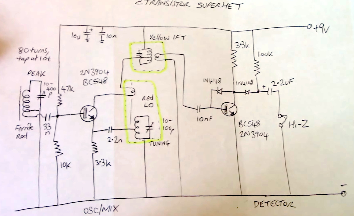
A modern portable radio will almost certainly use an all-in-one SDR-based chip, but in the golden age of the transistor radio the first stage of the receiver would be a single transistor that was simultaneously RF amplifier, oscillator, and mixer. The circuit in the video below does this , with a ferrite rod, the familiar red-cored oscillator coil, and a yellow-cored IF transformer filtering out the 455 kHz mixer product between oscillator and signal.
There would normally follow at least one more transistor amplifying the 455 kHz signal, but instead the next device is both a detector and an audio amplifier. Back in the day that would have been a germanium point contact diode, but now the transistor has a pair of 1N4148s in its biasing. We’re guessing this applies a DC bias to counteract the relatively high forward voltage of a silicon diode, but we could be wrong.
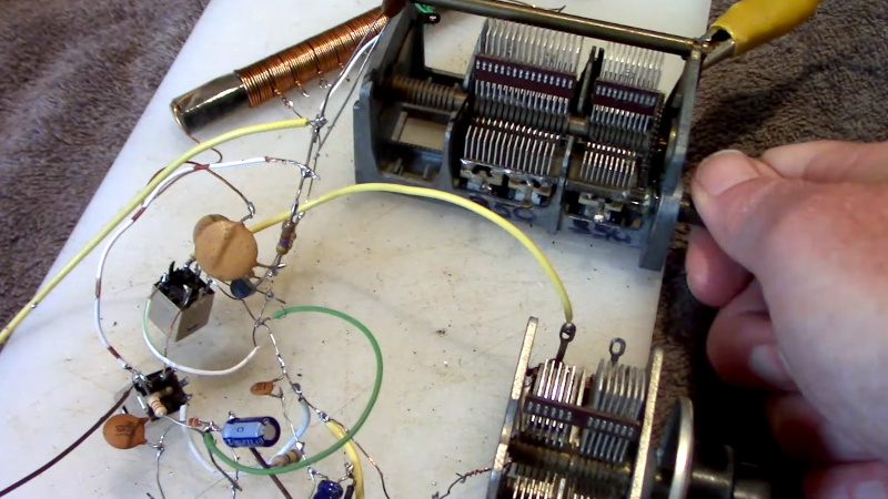
We like this radio for its unexpected simplicity and clever design, but also because he’s built it spiderweb-style. We never expected to see a superhet this simple, and even if you have no desire to build a radio we hope you’ll appreciate the ingenuity of using simple transistors to the max.


Simple if you can source the now overpriced varicaps and IF transformers. It’s been years since there was anything containing these that I would have been able to scrap for them.
Hi, variable capacitor, I guess. An DIY substitute can be made at home, in principle.
By varicap, the variable capacity diode is often being associated to.
The small transformers with the iron core on a screw are hard to get by, I agree.
Check your local hamfest. There are almost always people there with boxes of old parts from stuff they’ve taken apart. The low voltage variable capacitors needed for a receiver are usually quite cheap, but you will have to dig through boxes of junk to find them.
A lot simpler if the static circiit diagram and build is not presented as a video.
yeah the good part of the article is the screencap of the schematic :)
I recall a regenerative superhet project that was in a 70’s era Boy Scout Radio Merit Badge handbook.
In this project, the first stage after the amplifier was a regenerative detector.
“I recall a regenerative superhet project that was in a 70’s era Boy Scout Radio Merit Badge handbook…”
A reference / link to this complete project would be deeply appreciated.
After some diligent (I thought) searching (but, admittedly, not being a search-engine ninja) I cannot find it. At all.
Many thanks for any and all help.
Nice video and a very good minimalist demonstration of what can be done with very few components. Earl “Madman” Muntz would have been proud–no need to “Muntz” that radio with his diagonal cutters!
73!
I love Peter’s work. Before I even saw who the video was from, I had a feeling it was him.
Depends on the oscillators and whether you want the thing to be frequency-agile. I’ve seen random configurations of inductors and some corrosion spontaneously receive strong local stations, so while not necessarily being het, I think it can be done minimally.
As someone else mentioned, variable capacitors are quite expensive nowadays (when you can find them), because we just dont use them anymore for anything…
The big models are nolonger common,
but can sometimes be bought in specialized ham radio shops or antique radio shops.
Radio amateurs still have a need them for tuning of magnetic loop antennas or building linear amplifiers.
As for variable capacitors themselves,
the small plastic type in a white or translucent chassis is still available (more or less).
It’s the 500 pf type, with some smaller extra pins for 47 pf, 16 pf etc.
They were used in pocket radios.
https://commons.wikimedia.org/wiki/File:Universum_UR_1886_-_tuner_part_-_variable_capacitor-2252.jpg
A few decades ago, the 500 pf models in a “Pertinax” hard paper chassis were still widely available.
They were commonly used for detector receivers (crystal radios).
Talk to a local ham 50+. Chances are his/her junk box will have the vari caps and perhaps even the transformers.
You can use regular diodes (or LEDs) as varicaps.
There is an Etsy shop that makes beautiful variable capacitors- Armstrongradio
https://www.etsy.com/shop/armstrongradio
OK, fair enough minimalist design but…
The whole point of a superhet was to provide multiple amplification stages at a fixed frequency. This was an improvement over the earlier TRF designs that required each stage of amplification before the detector to operate at the tuned frequency, thus requiring a multi-ganged variable capacitor and careful alignment of each stage throughout the tuning range to keep the whole setup operating linearly.
A superhet with zero IF amplification stages seems pointless – in this case a TRF receiver would be simpler, require fewer components, and have no performance penalty.
I am 68 now and I use to build these radios in the 70’s back in Sri Lanka. The circuits came from a guy who made a business out of publishing these circuits as a booklet. So I progressed from a simple diode only radio with a large coil all way to 7 transistor radio. I had real fun and ready start again! Thanks for this post.
Collector current is a non-linear function of base-emitter voltage – that nonlinearity enables mixing and creation of intermediate frequency. Base potential comes from received radio signal, emitter potential from local oscillator. And winding connected to collector, magnetically coupled with local oscillator’s winding, is to provide feedback so LO can work.
I neat project I remember seeing in an electronic hobbyist magazine in the 1980s was a free power superheterodyne radio made from a small handful of BJTs. One tank circuit was tuned to a strong nearby station and that was rectified using transistors in lieu of Schottky diodes. The reset was fairly conventional loopstick based superheterodyne receiver. I don’t recall exactly where Imsaw the project. It was one of the then popular pulp paper electronics hobby magazines.
That was supposed to be 1970s in fhe paragraph above.