If you’ve ever used an NE602 or similar IC to build a radio, you might have noticed that the datasheet has a “gilbert cell” mixer. What is that? [Electronics for the Inquisitive Experimenter] explains them in a recent video. The gilbert cell is a multiplier, and multiplying two waveforms will work to mix them together.
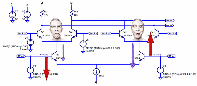
At the heart of the gilbert cell is essentially three differential amplifiers that share a common current source. The video shows LTSpice simulations of the circuits as he explains them.
One reason these work well on ICs is that they require very closely-matched transistors. In real life, it is hard to get transistors that match exactly. But when they are all on the same slab of silicon, it is fairly straightforward.
What we really like is that after simulating and explaining the circuit, he explains why multipliers mix signals, then builds a real circuit on the bench using discrete transistors and matched transistor arrays. There is a bit of trigonometry in the explanation, but nothing too difficult.
Of course, the most common application of differential amplifiers is the op amp. The NE602 is out of production, sadly, but if you can find any, they make dandy receivers.


AD831, MC1496 are also active RF mixers, but are different enough (from SA602) to require significant redesign (and have power requirements unfavorable for portable equipment).
I liked his approach to the Gilbert Cell, but when it came time to explain the mixing, he did what most people do and just provided the trig equations. They are, of course, correct, but If the objective is an intuitive understanding of the circuit, you really need to go beyond the trig. In spite of using many NE602s over the years, I struggled to understand the Gilbert cell. Finally, understanding came to me. I had to break the function up into three areas: mixing, balancing out of the RF, and balancing out of the LO. Here is how I came to understand this circuit: https://soldersmoke.blogspot.com/2021/11/how-to-understand-ne-602-and-gilbert.html#comment-form
your linked article is interesting, though it seems to be using the ‘602 more like a diode mixer (i.e. driving LO so hard that it is effectively a square wave) rather than as a Gilbert cell using the linear region of the transistors. I wonder if that was the usual way ‘602 were used — like a diode mixer but obviating the magnetics.
I have recently ordered a few NE602/SA612 equivalent parts with branding of a Chinese manufacturer to check out so while it is obsolete from NXP with a bit of luck it lives on elsewhere.
So we get a cheesy musical theatre reference, a shout out to Jesus, but no mention of one of the greats of our industry, Barrie Gilbert? That’s a choice, I guess.
The Vout vs Vrfin depicted at 10:13 (i.e. in VCA mode) looks like a non-linear relation. I wonder why that is, and is suggests there would be unwanted harmonics to filter out. Not as much with a diode mixer, but some nonetheless.
You can linearize each differential pair by adding a small resistance in the emitter leads. I did this in my implementation of the Phase Locked Loop FM Stereo Demodulator (1970) to reduce phase jitter due to subharmonics of 19 kHz in the audio.