Printing metal as easily as it is to print with thermoplastics has been a dream for a very long time, with options for hobbyists being very scarce. This is something which [Rotoforge] seeks to change, using little more than an old Ender 3 FDM printer and some ingenuity. Best of all is that the approach on which they have been working for the past year does not require high temperature, molten metals and no fussing about with powdered metal.
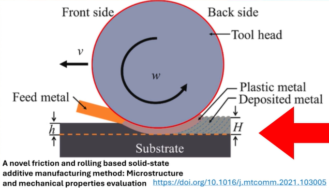
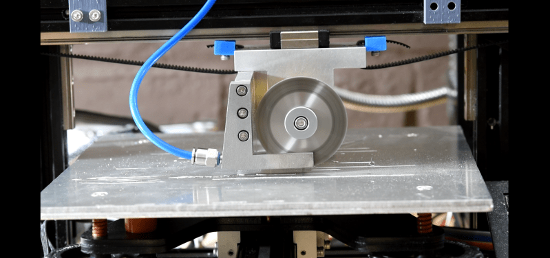
Rather than an extruder that melts a thermoplastic filament, their setup uses metal wire that is fed into a friction welding tool head, the details of which are covered in the video as well as on the GitHub project page. Unlike their previous setup which we reported on last year, this new setup is both safer and much riskier. While there’s no more molten metal, instead a very loud and very fast spinning disk is used to provide the friction required for friction welding, specifically friction and rolling-based additive manufacturing (FRAM) as in the cited 2021 paper by [Ruishan Xie] et al. in Materials Today Communications. By the same lead author there’s also a 2025 paper that explores more complex implementations of FRAM.
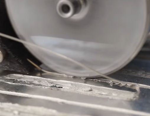
With this method the feed wire (e.g. aluminium) will experience plastic shear, causing it to become somewhat fluid and capable of adhering to other surfaces. This same method can be used for other materials, including plastics and glass. As can be seen in the video, FRAM certainly seems viable, though it is a veritable rabbit hole of complications since you’re dealing with a high-velocity engineering challenge.
Here’s where [Rotoforge] found that slitting saws are a good, off-the-shelf option as they have basically the same high-speed-but-safely requirements. This left the motor part, which has to keep the friction wheel going. After a lot of trial and mostly error, it was found that the motor in a Dremel tool provided the solution in the form of a universal AC motor. Unlike brush-less DC motors, these AC motors are far more simpler, cheaper and can keep up a constant speed much better, which is probably why they’re still used in power tools everywhere. Ergo some cheap Vevor flex-shaft grinders were bought and adapted for some FRAM purposes.
Initial experiments with Al1100 aluminium alloy showed very good layer adhesion, to the point that they were very similar to a solid bar of aluminium. Due to the layered nature of the prints, they perform better than solid Al1100 parts in some tests. Thus the next challenge was to try more advanced printing techniques than a single straight line, which posed the bigger challenge and is where the basic Ender 3-based prototype met its match.
Next a fourth axis will be added to hopefully resolve some of the issues encountered with the current prototype, along with a host of other improvements to make printing more reliable and versatile. Although it’s clearly still early days for FRAM, it is rather exciting that even in a hobby setting without massive monetary investment it’s already possible to do this much.
Of course, it should definitely be said that eye- and hearing protection are absolute requirements if you intend to do some FRAM printing yourself. The video gives some idea of how loud the process is, and high-speed discs and wheels together with metalworking always introduce the exciting possibility of high-velocity shrapnel.


Great video. Not sure where this will lead you, but I enjoyed the explanations of what you had done. Look forward to seeing how you progress (or not).
One could also add Vibration-Assisted Friction Stir (VAFSP/VAFSAM) to the mix as well.
I think they make these tattoo-gun-like reciprocating engravers with carbide tip. maybe that could be used to tattoo more aluminum into the previous layers?
looks like a great way to make metal croissants, but straight.
There is a related process called “Additive Friction Stir Deposition” from a local company called MELD.
https://www.meldmanufacturing.com/
It is a large scale process.
We also bought where I work a Mantel 3D printer, which is a hybrid design using both a paste that is printed, and an endmill to get precision. The system, including the over, was $400k
https://mantle3d.com/
Why wouldn’t you just use a belt drive system so that you could have a small wheel spinning fast driven by a larger wheel so the motor doesn’t have to go so fast to get the speed you need at the depositing head. It would also seem to give you a lot better fine control over where the wheel moves. It seems like it would also give you cleaner lines and nicer edges. It looks pretty ratty the way it is now.
OP here, we did try this.
It may still be a future design.
we were trying to simplify everything as much as possible to make getting started as simple, cheap, and accessible as possible.
the issue with gear/belt/chain drives is typically their RPM/wear life trade off.
even if we gear up a motor to a higher output RPM we need to have a drive system which can tolerate that higher RPM.
Gears/belts/chains that operate >30K RPM at the output are short lived or extremely expensive.
Power is cheap from Universal motors.
so we just got the biggest universal motor we could buy at the lowest cost/watt, and used the power at speed to keep the metal flowing. same trick as CNC milling machines typically use.
I would think, if you’re FRICTION welding, torque is at least as important as speed, and belt drives are terrible at delivering torque against resistance. If the main wheel were belt-driven, I’m having a hard time seeing how it wouldn’t start slipping as soon as it made contact with the work surface.
This seems like one of those things where, if you manage to perfectly calibrate all of its complex systems, it can work pretty great… until the first time something slips even a tiny bit out of alignment, and then it almost instantly becomes a catastrophic failure that cascades to completely obliterate not only the output, but the entire machine. And if they’re not careful, perhaps the operator as well.