Today in power electronics, the folks over at Texas Instruments have put together a video covering low-dropout (LDO) linear regulators.
For a hacker, power is pretty fundamental, so it behooves us to know a little bit about what our options are when it comes time to regulate power to our projects. In this video [Alex Hanson] from Texas Instruments runs us through the linear voltage regulators known as low-dropout regulators (LDOs). It turns out that LDOs are often a poor choice for voltage regulation because they are inefficient when compared to switching regulator alternatives and can be more expensive too.
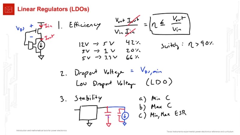
So when might you use an LDO? In very low power situations where heat and efficiency doesn’t matter very much. LDOs operate best when the input voltage is very near the output voltage and when current demands are low (roughly speaking less than ~50 mA is okay, ~500 mA is maximum, and some applications will support 1 to 3 A, although not with great efficiency and in this case thermal emissions — or magic smoke! — will become an issue).
What LDOs bring to the table is relatively clean and low-noise voltage as well as low dropout voltage (the minimum difference between the input and output voltage needed for regulation), which is their defining feature. What’s more with an appropriate output capacitor they can react quickly to load changes and they usually emit minimal EMI. LDOs are not about efficiency, they are about quality, simplicity, and control.
You might like to read more about when linear regulators might be the right choice or what your other options are.


“LDOs operate best when the input voltage is very near the output voltage.”
Even though many LDOs boast minimum dropout voltage of 0.1 V or less, usually the best regulation and lowest output noise is specified for a voltage drop of 0.5 V or 1 V.
I designed a board for my current employer about 3 years ago with a then-new TI part, it was a very low Iq 30nA LDO to drop 3V from a primary lithium cell to 1.8V. It was a very small DFN4 or whatever part. 1mm X 1mm iirc?
Sadly the LDO never worked. It just didn’t work at all, the board was okay, schematics were okay, the assembly house too did their job. It just didn’t work. The rest of the board was flawless.
I heard quite an earful but I was told to work on the revision board with a different part right away so I could never figure out what was wrong with it…
I’m just curious if that had ever happened to anyone here. Everything being correct, schematics, layout, footprint, assembly house swore they followed everything to the letter. And still it didn’t work?
What do you mean, one didn’t work, or none of the manufactured units worked?
A common failure mode is overvoltage on hot plugging, exacerbated by ceramic capacitor nonlinearity. Perhaps this is what bit you.
I’ve never had a problem with linear regulators – in fact, my usual move is to replace the failed switching supply circuit with a linear because they’re so reliable (unlike many of my switch mode circuits)
I haven’t experienced issues with an LDO not working properly, but I did have a D-type flip-flop that I couldn’t get to work properly. I think it was actually a TI product. Anyway, even after contacting company technicians and providing my schematic, they couldn’t identify the problem either. 🤣🤔
Some LDOs require a minimum load to work.
But in most cases it is a user error. I struggled for a few weeks to find out why a board I designed had a buck converter that would regulate out of the designed range for some boards and within for others.
One day just going over the schematic one more time, I noticed that one capacitor was 22nF instead of 22pF as recommended. Changing that one small capacitor fixed everything.
So yeah, double check everything, and I really mean everything.
It’s good to make sure the basics are covered. But if you know what “LDO” means you don’t need this particular video.
It’s been almost two decades now, but I was impressed by the low noise and high current from TI’s TPS74901. Our application demanded near thermal noise performance, but called for 11+ amps at 1.8 volts. A switcher providing 2.8 volts followed by four ‘74901s in parallel did the trick and saved the project: undetectable switcher noise on the load side of the LDOs. Sure, just 60% efficiency, but burning a dozen watts over four heatsinks is a reasonable price to pay for thermal noise floor performance.
If heat is such an issue couldn’t you just add a fan?
Sure but if you have a battery powered application you are burning unnecessary power and shortening run time. Also heat sink are pretty large so if space is a concern, thats a design issue as well.
Passive cooling is always preferable over fans. Those have several issues, most obviously audible noise, and reliability. The years go by and dust accumulates.
Granted this is within the last decade, not two; but I made a low-noise multi-output power module from dual-phase switching regulators, and a bit of extra filtering (LCLC). Comparable or higher ratings (what was it, over 250W total, including -5, 1.2, 1.8, etc. V, at up to 20 or 30A?). The low noise spec was mostly at high frequencies (20-200MHz), where a ~100µV ceiling was met. Responsible layout is needed, but a shield can was not required. That’s not exactly “thermal noise” levels (I needed a preamp to resolve it on my 8-bit DSO, but the supply was still 10 or 20dB above the amp’s noise floor), but a shield can and one more LC stage should do that.
Low frequencies are much harder to deal with; you can’t afford LC filtering so easily, and that’s where LDOs (or more traditional methods like a capacitor multiplier) can shine.
Obviously, SMPS emit a lot of “noise” around Fsw (and harmonics, and sometimes subharmonics), but not necessarily below there (or inbetween the peaks). PWM, by itself, can be very clean! But it does depend; contrast a well-made analog design, with a fixed-clock state machine design (basically, imagine using an MCU as controller + modulator) which is limited by temporal and voltage quantization (i.e. the PWM divider can only be so many counts, as can the ADC/DAC; it’ll have a broad noise spectrum like sigma-delta modulation). PSRR also depends on the modulator: a naive voltage-mode PWM modulator has output proportional to Vin, but a peak current mode controller has excellent PSRR. Output is improved with loop gain, but only within the controller’s bandwidth, which will be some fraction of Fsw (or even the output filter Fc!), and some fraction further before that gain is substantial (because ~20dB/dec slope).
LDOs have the same control problem, of course (loop gain is limited at AC); PSRR at typical Fsw’s can be pitiful, particularly at low drop. Special types offer extended performance, through alternative means (I haven’t researched if they’re using just highly tuned controls, or multiple stages, or internal filtering or what, but the specs, if they’re representative of real use, are impressive).
Many switching regulators boast Iq in the nanoamps, but that’s only when you turn the regulator off completely. There’s usually an Enable input to switch it. If you need to keep the voltage up to maintain a circuit in standby with minimal current consumption also in the low microamps, leaving a switching regulator on consumes more power than using a similarly sized low-Iq linear regulator.
Some switching regulators have a function that turns them off and on periodically as the load decreases, but that’s mostly because they’re not the most efficient parts to begin with – they have to have it in order to give reasonable performance. You get worse regulation, greater parts count, and usually higher cost than the simpler LDO – with the advantage of greater efficiency when the device is in active mode.
So, efficiency matters, but which one is actually more efficient depends on the duty cycle of your device. Where does it spend most of its energy – sleep or active duty?