 Part of any self-respecting Smart Home, smart relays are useful for switching and monitoring loads that do not plug into an outlet. This also makes them a lot more integrated, and thus, a long lifespan is very welcome. Unfortunately, the popular Shelly 2.5 smart relays seem to be having a bit of a design flaw as they’re dying in droves once their 2-year warranty period is up. The cause and repair are covered in a recent [VoltLog] video on YouTube.
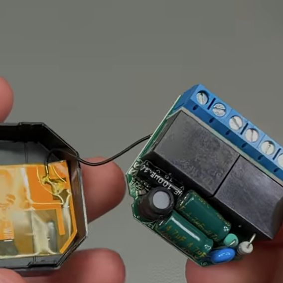
As noted in the Shelly documentation for the device, it’s a very compact form factor device, with screw terminals, two relays, and three fairly large electrolytic capacitors sharing very little space with the rest of the components. The apparent flaw comes in the form of these capacitors failing, with the video showing that one 100 µF capacitor has a massively increased ESR, likely due to electrolyte venting. This results in the observed symptoms, such as WiFi connectivity issues and audible hissing, the latter of which is demonstrated in the video.
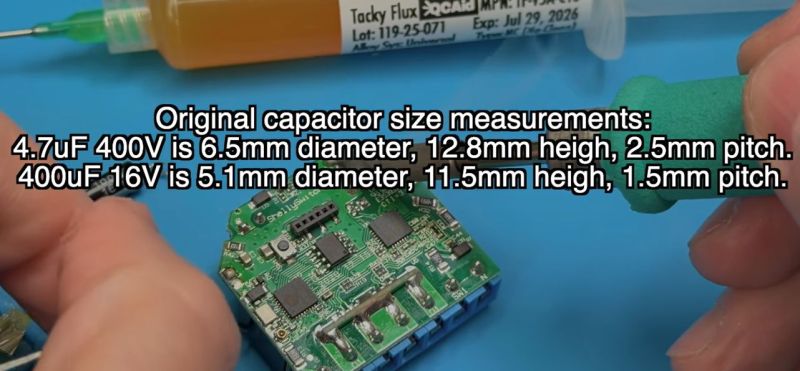
Due to the cramped space, the replacement capacitors need to be at least as small as listed in the video and in the top screenshot, though mind the typo as ‘400µF’ has to be ‘100µF’. This limitation posed a bit of a problem, as for the two 400V, 4.7 µF capacitors, there aren’t that many options in that form factor. The original capacitors are definitely B- or C-grade ones, with the two large capacitors Chongx branded, being a well-known budget capacitor brand. The other capacitor’s branding cannot be made out in the video, but is likely also Chongx or a similar, less well-regarded Chinese brand.
For the replacements, a Nippon Chemicon capacitor was picked for the 100 µF capacitor, and Ymin-branded capacitors to fit within the size limitations. Picking Ymin over a second Nippon Chemicon set or similar was due to these unfortunate sizing limitations, but these Ymin replacement capacitors had the best datasheet of the options on LCSC. All of these capacitors have to be rated for 105°C, for obvious reasons.
Although it’s not easy to say for certain what caused these capacitors to fail so quickly without more data, it seems likely that having the SMPS circuitry for the 3.3V rail bunched up cozily with the three electrolytic capacitors and what looks like two load resistors inside the cramped enclosure with no clear ventilation holes does little to help the electrolytic capacitors hit their listed MTBF hours. Hopefully, using the new capacitors, these relays will last longer than 2-3 years before another recapping is needed.


Sounds like they were engineered perfectly to maximum profits. In the short term.
Selling subscriptions is so 2020, now we’re full circle back to built-in obsolescence to keep revenue streams on-going.
Electrolytic caps have well characterized life times, and running them hot is a very good way to ensure a lifetime predictably in the couple year only range. As is using cheap caps.
Not uncommonly, if you’re running an electrolytic near/at it’s max rated temp, it’s lifetime will be measured in single digit thousand hours, I.e. under 2 years.
Oh, and also a big source of heat is actually the capacitor itself. Smaller / cheaper caps will have higher esr, which directly translates into internal heating if they’re carrying a decent load.
For power supply filter caps in particular, you don’t want to go with the smallest caps with the needed capacity, as those will often be the highest esr and have lower lifetimes.
The ECO mode reduces the temperature of the Shelly by 5-10C.
I assume this will increase the lifespan.
Often, just using two caps, each half the capacity, in parallel will save the day. Total ESR is lower, and the surface area for cooling is increased. Board layout is more flexible and even the total inductance is lower. win-win-win, for marginal increase in board area and cost.
https://www.smarthomejetzt.de/wp-content/uploads/2021/04/shelly_2.5_hinter_schalter_dose_einbau-scaled.jpg
Using relays with WAGO terminals, what could possibly go wrong /s
(Except for a house fire from melted or misconnected terminal.)
Was the terminal melted, or misconnected? Did it melt because it was misconnected? Did it melt, but not due to being misconnected? Hard to know what point you are trying to make from a photo without any context.
The picture doesn’t look wrong. Maybe I’m missing the point, would you mind explaining it more?
OP doesnt like it
Apparently, and I genuinely would like to know why. I switched to WAGO a few years back and have been nothing but happy so far. Aside from the price, I love them.
It is an electricians disdain of them because they have a way they do things and they feel these are unnecessary. They are also popular with the DIY crowd so mistakes happen more frequently. I use them because the smart switches require more ‘behind the switch’ space and they help keep things tidy. I asked a master electrician about them and my work, he said they are fine, just not necessary. If I possessed their level of skill I would probably agree with them.
I am not an expert but i think part of the reason they have a good reputation in europe is that more people have seen the kind where you push on a little lever to get it to latch firmly. And part of the reason they have a bad reputation in USA is every electrician here has met pure spring-loaded connectors, like “back stabbing” on an electrical receptacle. I think sometimes people don’t realize they’re talking about two different products.
WAGO clamp terminals have been shown to be more reliable in every area than their contemporary screw terminal blocks, so I’m not sure what this means.
The only reason we don’t use them everywhere is because they’re more expensive.
Isnt that just as likely to happen with screw terminals? Even more so, because it takes more effort and care to ensure a screw terminal properly secures the conductor?
Shh, don’t bring facts into this!
Please explain, I combined exactly the same. I can’t spot any problem there. Wago has a good reputation, afaik
Screw terminals opperate on the principle of positive expansion pressure. In layman’s terms when a wire heats up, terminal parts also do. When screw heats up it tends to expand, clamping the wire tighter into the terminal. This prevents bad connections. Wago is the exact opposite – because it uses spring contacts, when the wire heats up, those springs will expand, get looser and create even worse connection. This resuls in a thermal runaway event and a fire. Robotics team (I was a member of) at Regensburg University actually tested and confirmed this phenomenae.
Did you publish the results of your tests? Were they peer reviewed? Because it sounds dumb. Nothing in your photo looks like a house fire. Nothing is burned or melted.
I’d be interested in a paper, too. But why dumb? I mean, discussing Wago in a Shelly thread is not the right place. But Rick might have a point. At first sight, I wouldn’t trust Wago conns, either. But some electrician pals said it’ll be fine. Had no problems charging my Tesla with these in the line, yet.
This photo was taken before the fire happened.
Replying to Rick. What fire? And was it directly due to the Wago connectors? You are posting unsubstantiated nonsense. What exactly are you trying to say? If these are bad, where is your evidence?
Form factor too small…
Too much heat…….
Not enough space. …
They get the Apple Award for Best Planned Obsolescence.
I’ve had a number of Smart Switches fail for the same reason – dried out electrolytic cap(s). I suspect the main reason for this is the heat generated by the relays. If the switch is on for an extended period, there’s 2 x 0.5 watts of power from the relay coils that needs to be dissipated in a very tight space with no ventilation.
Of course, once the relay has been switched on, the full coil voltage doesn’t need to be maintained to keep the relay on. The datasheet for those relays quotes the min hold-in voltage for a 5 volt relay as 0.25 volts!
A solution I’ve tried with a Tasmota-flashed smart switch is to drive the relay from a PWM output. Turn the relay on with 100% PWM, then ramp it down to 20%. For this case, the dissipation would drop to 40 milliwatts.
Wow! I had no idea about “min hold-in voltage”. I’ve always been keen on the toggle relay — you pulse a solenoid that turn the relay on or off, and it holds it on its own. But if you can hold the state with a smaller wattage, that’s a good bit of advantage without the complexity / cost of the special toggle relay.
Built way too close to cost.
On a side note Load Life or Lifetime Hours listed on the electrolytic capacitor spec sheets are the total rated time a cap can sustain heat spikes over it’s lifetime (please correct me if there’s a nuance I missed). Not an MTTF rating.
To be fair to Chongx, if you’re building at minimum cost there may be a legitimate reason for the component failure.
MTBF for an electrolytic capacitor is irrelevant since ESR rise will be the predominant failure mechanism. This is stated in hours. At 105C can be 2000, while at 45C can be 128,000 hours. Improved (lower) thermal conditions and lower ripple stress need to be baked into the design.
Shelly 1 Mini Gen3 uses Aishi 3.3y 400V caps.
I’m still fascinated by the tiny Shelly branded ESP and wonder why there is still an external 40MHz osc…
Materials are well understood now, with caps there is a clear way and method to time the life of a product by stressing these parts. Same with LED lighting. Heat is the enemy, heat here is your friend.
Style, gotta have the beveled corners! No looks with a square box. This crammed things too far. Made for exact part sizes, replacements or better spec parts won’t fit.
Thirdly I question the line isolation gap on the tiny board from the external relay contacts. There are safety standards here.
I wasn’t aware of these nifty things, I’ll look into bigger sized ones though.
I have 8 of these behind light switches around the house for 3 years now, that headline was a great way to start the Monday.
None of them failed yet. The maximum load on them is 2x11W led light bulb though. They were on tasmota for most of the time, but last year I migrated everything to ESPHome. They have low power mode enabled, but I think when there’s a lot of 2.4GHz noise, they switch to higher power mode, reporting 55-60 degrees celsius while idling, going up from 40-45.
One of them is constantly at 60 degrees, going up to 67-68 when running the bathroom fan. It had this issue that sometimes when I turned the fan off, the shelly device rebooted. If I understand this correctly, this was because of the inductive load of the fan spiking the voltage when turning it off. I connected a Shelly RC Snubber and that solved this problem completely, but I think the spikes might have wore the caps out or something and that’s why it’s in constant high power mode.
I might just wait for one of them to die, and then replace all of them instead of replacing the caps. While I’m comfortable with soldering and repairing stuff like this, I’d rather not have these kind of repairs in my walls on 230 Volts.