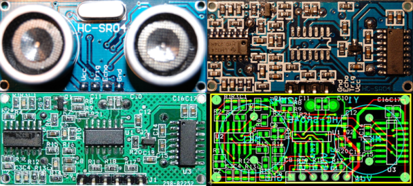
[Emil] got his hands on a dozen HC-SR04 ultrasonic sensors, but wasn’t too happy with their performance. Rather than give up, he reverse engineered the sensor and built an improved version. Hackers, Makers, and robotics enthusiasts have had easy access to standard sonar platforms since the early 1980’s, when Polaroid began selling their 6500 sonar modules. A number of companies have released sonar boards since then, notably The Parallax Ping))) module. The HC-SR04 appeared on the market a few years back as a low-cost alternative of the Ping.
[Emil] found that the HC-SR04 would work reliably on hard surfaces as far as 4 meters away from the sensor. However, he got a lot of bad data back when using soft sided targets, or when no target was present at all. [Emil] reverse engineered the schematic of the HC-SR04 and found some interesting design decisions. A Max232 RS-232 converter chip is used for its +-12V +-10V charge pumps. The charge pumps are connected to create 24V 20V at the ultrasonic transmitter. A mask programmed microcontroller manages the entire unit, commanding the ultrasonic transmitter to send 40Khz pulses, and listening for returns on the receive side of the system. [Emil] believes the micro is running in polled mode, due to the fact that it sometimes misses pulses. Even worse, the micro runs on an unmarked 27MHz crystal which had quite a bit of drift.
[Emil] solved these problems by creating his own PCB with an ATtiny24 and a 12MHz crystal. He increased the pin count from 4 to 6, allowing the ATtiny to be programmed in circuit, as well as opening the door to I2C and SPI operation. To build the boards up, [Emil] first solders his micro and crystal. He then uses a hot air gun to move all the components from the HC-SR04 board to his own. The new boards are still being tested, but [Emil] has posted his PCB and BOM data. He’s also promised to post his AVR code when it is available.


