Since we all have wires running throughout our houses to provide mains power, there’s a number of devices that piggyback on mains lines for communication. For his thesis project, [Haris Andrianakis] developed his own power line communication system.
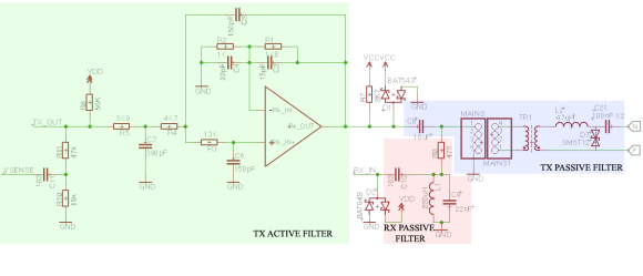
The basic principle of the system is to inject a signal onto the power lines at a much higher frequency than the 50 or 60 Hz of the AC power itself. Using both active and passive filters, the signal can be separated from the AC power and decoded. This system uses frequency-shift keying to encode data. This part is done by a ST7540 modem that’s designed for power line applications. The modem is controlled over SPI by an ATmega168 microcontroller.
[Haris]’ write up goes into detail about some of the challenges he faced, and how to protect the device from the high voltages present. The final result is a remote display for a weigh scale, which communicates over the power line. Schematics, PCB layout, and software are all available.