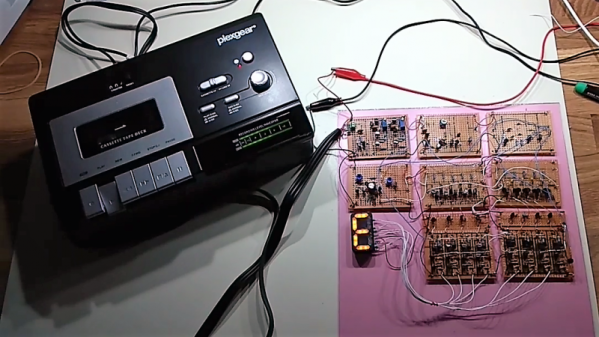
Those who were around for the pre-floppy days of computer mass storage were likely to have made the mistake of slipping a cassette tape containing data into a stereo tape deck. Instead of hearing the expected Awesome Mix, the speakers gave off an annoying bleat, warbling between two discordant tones and no doubt spoiling the mood.
What you likely heard was the Kansas City standard, an early attempt to provide the budding microcomputer industry with a mass-storage standard. It was successful enough that you can still find KCS tapes in need of decoding to this day. That job would be a snap with a microcontroller, which is exactly why [matseng] chose to do it the hard way and built a KCS decoder with nothing but discrete components.
The goal was to decode the frequency-shift-keyed (FSK) signal into an 8-bit parallel output, and maybe drive a seven-segment display as the characters came off the tape at a screaming 300 baud. Not an IC is in sight in the schematics; as [matseng] says, it’s nothing but “Qs, Rs, and Cs.” All the amps, flip-flops, and counters needed are built from a forest of transistors, and even the seven-segment display is a DIY affair of LEDs in a 3D-printed and hot-glue frame. The video below shows the display doing its best to show the alphanumeric characters encoded on the audio tape. And for who absolutely need a dose of Arduino, [matseng] used one along with a dead-bug low-pass filter to emulate KCS signals, for easier development.
We always appreciate hackers who take the road less traveled to arrive at a solution, but if you’re pressed for time to decode some KCS tapes, fear not – all you need is a PC and Audacity.


