 [Brian] adores his GW Instek GPC-1850D power supply, but it’s annoyingly loud and disruptive to his audio projects. The thing works great, so he decided to regulate the fan’s speed based on usage level to save his sanity.
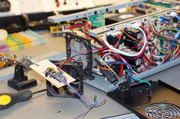
Once [Brian] got under the hood, he found that it actually has four separate heatsinks: one for the bridge rectifiers and one for each power transistor on the three output channels. The heatsinks are electrically and thermally isolated from each other and change temperature based on the channel being used.
[Brian] and his associates had several Microchip MCP9803 temperature sensors kicking around the lab from previous projects, so they put one on each heatsink. The great thing about these is their address selection pins which let all four of them sit together on the I²C bus to Arduinoville. Each sensor is insulated and clamped to its heatsink with a piece of meccano and a dab of thermal paste.
[Brian] used an Arduino Mini and built the circuit on stripboard. The fan runs at 24V, so he’s sharing that with the Arduino through a 7805. He controls the speed of the fan with PWM from the Arduino fed through a MOSFET. The Arduino reads from each sensor and determines which one is hottest. [Brian] wanted the fan to run at all times, so he set a base speed of 20%. When the heatsinks reach 30°C/86°F, the fan speed is increased to 40%. After that, the speed increases at 5°C/9°F intervals until it reaches max speed at 65°C/149°F.
You can grab the code and schematic from [Brian]’s repo. If you want to study your heatsinks, build this heatsink tester first.


