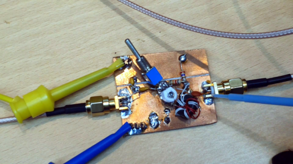
As electronics rely more and more on ICs, subtle details about discrete components get lost because we spend less time designing with them. For example, a relay seems like a simple component, but selecting the contact material optimally has a lot of nuance that people often forget. Another case of this is the Miller effect, explained in a recent video by the aptly named [Old Hack EE].
Put simply, the Miller effect — found in 1919 by [John Milton Miller] — is the change in input impedance of an inverting amplifier due to the gain’s effect on the parasitic capacitance between the amplifier’s input and output terminals. The parasitic capacitance acts like there is an additional capacitor in parallel with the parasitic capacitance that is equivalent to the parasitic capacitance multiplied by the gain. Since capacitors in parallel add, the equation for the Miller capacitance is C-AC where C is the parasitic capacitance, and A is the voltage gain which is always negative, so you might prefer to think of this as C+|A|C.