
Before we get into the how-to, we felt it would be appropriate to explain a little bit about how this came to be. As many of you may remember, a couple of months ago we attended CES 2010. While there, we also attended the It Won’t Stay in Vegas Blogger party and ended up meeting the guys from Woot. After all of us spent a little bit of time appreciating the open bar, a group of us stood ended up standing around and talking shop for a while. All of a sudden, a member of our group, Jeremy Grosser, proposed the idea that Hackaday and Woot form a partnership. Basically, they would give us a heads up on what they are going to sell and we would write up a how-to on how to do something cool or useful with that product. Then, when the day came for Woot to sell the product, we would post our how-to. What you are reading right now just so happens to be that idea in action, the first official partnership between Hackaday and Woot. In this how-to, we’ll be taking apart the Wowwee Rovio mobile webcam robot, adding some super-bright LEDs for better see-in-the-dark action, and see how some software called RoboRealm can give it a little bit of artificial intelligence.
If don’t have a Rovio yet, you should probably head over to Woot and pick one up so you can follow along. Also, be sure to pick up a copy of RoboRealm at deals.woot while you’re at it. It is important to note that while writing this how-to, we used a modified design of the Rovio Head-Mounted LED hack, posted to RoboCommunity by [Rudolph].
Parts
– 6 super-bright white LEDs (Ours were rated for 3.3v with an intensity of 7000mcd.)
– 1 2N2907 PNP Transistor (We found ours in a 15 transistor combo pack from RadioShack.)
– 1 22ohm resistor
– 1 2.2k ohm resistor
– 22g solid hookup wire
– RadioShack 3x2x1″ Project Enclosure (We used the plastic back panel as a place to mount our LEDs.)
– 5mm LED holders (Optional. We ended up using them to mount our LEDs in their poorly drilled holes.)
– Heat-shrink tubing (Optional, but recommended.)
– A small strip of perfboard
We picked up most of our parts from RadioShack, but these parts are so common that you should be able to pick them up from any electronics components store.
Disassembly
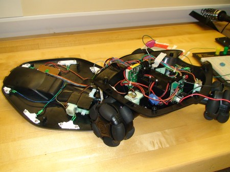
The first step towards giving our Rovio some much needed extra light is, of course, to disassemble it. After turning the Rovio upside down, remove the six phillips-head screws and carefully remove the top shell to gain access to the Rovio’s internals. While you won’t be able to fully detach the top shell, you should be able to lay it next to the bottom part of the Rovio as seen above.
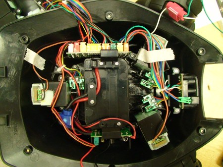
Inside of the Rovio, there are two main PCBs, the control board and the power supply board. For the purposes of this how-to, we will only need to modify the power supply board. To gain access to the power supply board, simply remove the two phillips-head screws that secure the board vertically. After you gain access to the board, you will then need to identify the ground and positive pads on the PCB. We will be tapping into these pads later to power our array of LEDs. One other item of interest to us is the white wire leading from the control board to the LED headlight board. This wire will allow us to control our new headlights through the Rovio’s web interface.
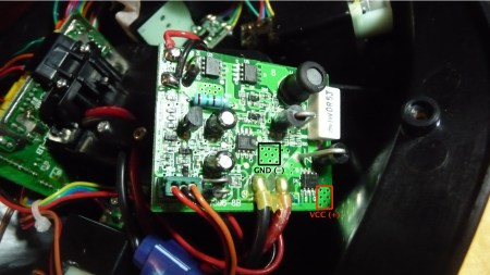
After firing up your soldering iron, you’ll need to solder two wires onto the power supply board. As you can see above, there are two areas with tiny little holes, allowing for easy access to both GND and VCC. After you have soldered both of these wires, screw the board back in and then turn your attention towards the white wire mentioned previously. After cutting the white wire, solder a length of hookup wire to the end of it and insulate it with appropriately sized heat-shrink tubing. Also, it’s probably a good idea to remove the LED headlight board entirely. This gives you three openings to run your wires out of from the Rovio to our new headlight panel. After you’ve removed the board, you can cut the wires leading to both the infrared LED and receiver. These function as a forward facing “radar” to alert the user if there are any obstacles ahead. We decided to salvage ours by placing them both in the new panel that we will soon be creating. If you choose to salvage your infrared “radar” as well, then remember to solder extension wires between the appropriate leads and the LED and receiver. We actually used some telephone tap connectors (from RadioShack) to extend the three wires leading to the infrared receiver, but soldering should work just fine. Now that you’re finished with all of the internal modifications to the Rovio, we can move on to the circuitry behind this hack.
The Circuit

In order to make sure that we can control our replacement LED headlights through Rovio’s web interface, we need to build a circuit that will detect when the headlights are triggered via the web interface and activate our headlights accordingly. To do this, we’ll use a PNP transistor to switch the ground of our headlight circuit. As you can see from the schematic above, the white wire that we mentioned earlier will be connected to the base of the transistor via a 2.2k resistor, the ground from the power supply board will be connected to the collector of the transistor, and the emitter of the transistor will be connected to the ground of the parallel array of LEDs. If you want to, you could probably add a few more LEDs to this design. Just remember, if you change the number or type of the LEDs, you will have to recalculate the value of the current-limiting resistor between VCC and the positive pin of the parallel LED array. After we’ve reviewed our schematic and we’re comfortable with it, we should be ready to breadboard.
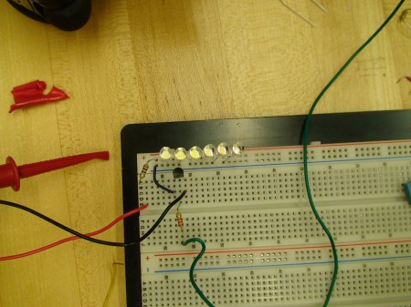
As you can see, there really isn’t that much to our circuit as far as components go. The black and red wires come directly from the power supply board. Our voltage reading was right around 6.5v. Please note that your voltage may vary depending on the charge of your Rovio’s NiMH battery. The green wire was soldered to the white wire inside of the Rovio, and controls whether the transistor lets the ground flow to the LEDs. We found that the best way to test this circuit while breadboarding was to turn on the Rovio and turn on and off the headlights using the web interface. After confirming that the circuit works consistently, you can go ahead and solder the circuit onto some perfboard and connect to the Rovio.
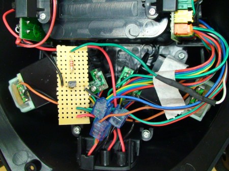
The circuit really doesn’t take up much space on the perfboard. We decided to use the extra space on our board as a makeshift terminal block to extend the infrared LED. While soldering the circuit onto the perfboard, be sure to remember the orientation of your transistor. If you accidentally put it in backwards, you could switch the collector and emitter, burning out the transistor. We mention this only because we actually did it the first time we assembled our board, and we ended up having to swap in a new transistor before reassembling the board. After you’ve assembled and verified that your circuit works, we can move on to assembling our headlight panel.
Drilling and Wiring
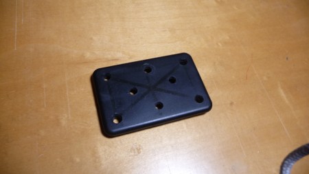
On your blank panel, carefully drill 8 holes in any configuration you would like. When drilling your holes, be sure to use a 3/16″ drill bit. While it is actually slightly smaller than a 5mm LED, you can rotate the drill once or twice around to widen the hole. The main thing is that you don’t want to make the holes too large for the LEDs, which, incidentally, we ended up doing. One of them was so wide that we had to change the placement of our LEDs to make sure that they all more or less fit.
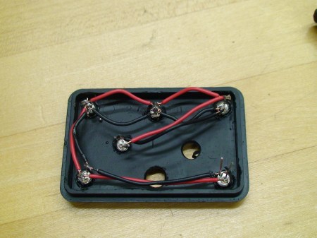
I don’t think that I need to get into too much detail here, but the major thing to remember is that the LEDs need to be wired in parallel. Also, be sure that you are connecting cathode to cathode and anode to anode, otherwise the whole circuit just won’t work. After you’ve completely assembled the panel, attach the wires the ground from your perfboard and the VCC from the power supply board to the circuit, and use the web interface to test that the LEDs get switched on when they’re supposed to be. If you decided to salvage the infrared “radar”, don’t forget to attach the infrared LED and receiver to the board in the two holes left over.
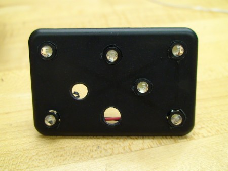
After you’ve finished with the drilling and wiring, you should be ready to attach the panel to the Rovio. While it was a little tricky for us, we were able to epoxy the panel to the underside of the front of the Rovio so that it looked like it was vertically mounted.
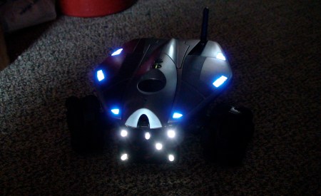
Now that your Rovio can see better in darker situations, lets take a look at RoboRealm.
RoboRealm

While investigating all of the different things that we could do with our Rovio, we stumbled upon a piece of software called RoboRealm. RoboRealm allows you to take video input from any webcam, including the Rovio, and run it through any number of different modules to process the images. After the images are processed, the software can even see if any pre-defined conditions are met, and if they are it will instruct the robot to act accordingly. Combine that visual input with the audio input/output on the Rovio, and you can do some pretty cool stuff. The interesting part about this software is that it officially supports the Rovio out of the box. We’ve had a chance to mess around with it a little bit, and as far as we can tell, it seems like pretty powerful software.
We already know all of the cool things that we want to do with this software and our Rovio, but we’re curious, what would you do with it? Leave us your answer in the comments, and if we see something that we find truly inspiring, we’ll do some research, write it up, and post a how-to explaining how to do it. Who knows, there might even be a brand new Rovio and a free copy of RoboRealm in it for the winner too…


Awesome! As if I needed more reasons to buy cool junk from Woot!
really guys?
i’m all for the partnership but the best you could up with was adding some leds and software that supports the web cam outta the box?
Yeah, cool idea.
All it needs now is a USB missile launcher, some motion tracking programming, and maybe a programmed external interface. You then will have the ultimate robotic neusance!
Back in early 2009 I was involved in a project that looked at the security and privacy implications of household robots, and the Rovio was one of the robots we investigated. You can read the paper and the FAQ here: https://www.cs.washington.edu/research/security/robots/
screw the led mod!
I would put a rfid tag reader on it and have it chase my cat around the house :-D
Better yet attach my green laser to the camera head and be able to play with my cat when I am not home with a nifty web interface :)
defiantly needs a speak jet chip attached to it though
What would i do with this? I am not a huge tech guy, but always excited about gadgets and love rc cars. I could see a lot of work with my kids, setting up chalenges for them to complete using various “flashcards” that the Rovio could read and then react accordingly. If I understand your description of the software correctly, could also use various sounds to pass instructions. My daughter is only 8 but this would seem to be an affordable and practical way to get her more involved with programing and logic. Great idea and excited about the partnership with woot!
It would be really cool if there’s a how-to that explains how to make the rovio a moving sentry that can shoot at intruders. The gun would probably have to be light, maybe a toy gun, airsoft, BB, or paintball?
O! Add a green laser to aim the gun with with some warning audio!
Wow, I always knew about woot! but don’t really check out the deals day by day… and this is a deal + a little hack is enough to make me buy it
But I agree with prem, LEDs is all you could come up with.. This isn’t ‘Pimp My robot’ there better be a follow up hack for this that is a little hack and a lot less slack!
This could be an interesting photovore type bot. Add some solar cells to the top surfaces, and use the camera/Roborealm to search for light spots. Sit until the battery charges, or move as needed. When night falls, use the high-beams and camera to wreak havoc! (ok, minor havoc, but imagine what this would do to your cat…) Still, there are some robo-behavioral experiments that could be done here, without the need for lots of BEAM circuitry…
I personally cannot afford this (quite cool) bot right now (I am sadly a poor college student) but I think this is an awesome idea and highly encourage such cooperation
Put wings on it. Make an attack drone.
Um, if im not mistaken, the schematic of the led circuit has the transistor backwards? In a switching PNP transistor the collector goes to ground. (I just remember the arrow points to ground)
And I agree. LED’s and special software! The software does look cool. But the LED’s could have been done a little better. I mean might as well duct tape LEd’s on the thing and call it a hack. Maybe if the case was modified to support more LED’s in the front or on the camera itself. I dont think where it is helps seeing when pointed up?
p.s. woot and hackaday, great idea. Cant wait to see a better hack next time ;)
Personally, I would program it to emulate the turrets from Portal.
Walk in “Hello, Friend”. When it loses sight of you “Are you still there?”, or maybe “Target lost”.
Sorry for double post. Just wanted to point out that hackaday already had a LED hack for the Rovio. That envoled putting led’s next to the camera.
http://hackaday.com/2008/10/20/rovio-teardown/
They already mentioned that this was a modified version of http://hackaday.com/2008/10/20/rovio-teardown/
For super stealth, why not use infrared LEDs to see in the dark instead?
I’m thinking of making a dog mod. sure it’ll take while to set up, but have the thing act like a virtual pet.
I wonder if I could mod it with blue tooth so it can attempt to play xbox games. :)
have it get all upset when I tell it that it can’t join my friends and I playing guitar hero.
I’m sorry, but that schematic has a lot wrong..
Unless the “WHITE” line (which you’re using a GROUND symbol for??) goes negative relative to GND, that won’t work as advertised. The Base-Emitter (NP) junction of a PNP transistor behaves like an diode, in other words current will flow through the Base-Emitter junction (and thus the transistor) when the Base is about 0.6V lower than the Emitter. As pRoFiT pointed out, if the transistor is placed upside-down so the emitter is facing the LEDs, it will function.
Also, using LEDs in parallel like that is risky, since the voltage drop for each LED may vary. The preferred method for wiring multiple LEDs is in series with a current-regulated supply. When a current-regulated supply or a high enough voltage isn’t available, you should use a resistor for each LED to avoid problems with different voltage drops.
The rest is style nitpicks: there should be junction points where the LED pins connect to their respective “bus” lines, and not that it matters electrically but why is Vcc drawn lower than ground?
Sorry for all the negativity, I hope this has been constructive criticism.. <3
This circuit is TERRIBLE. For one, the switching transistor is backwards (should be an NPN or flipped.) Second, and more importantly, you have 6 LEDs in parallel. Since the cutoff voltage of each LED can vary, the current through each LED will be wildly different, which will cause them to fail. Each LED should really have its own current-limiting resistor.
Aha! Taking a closer look at the breadboard picture, I see the transistor is in fact upside-down from its schematic representation.
It would be great to get my hands on one of these and teach it to play tictactoe or rock paper scissors (via audio output).
Or just program it to chase my dog around, muahaha.
what is wrong with you hackaday!?
you added white leds!
should rip out the ir filters and add some nir diodes!
hm… is there a blimp version yet?
Game using Rovio, Roborealm and human players.
Using Roborealm and fiducial markers – and an Augmented Reality approach (buzzword overload!).
Make a number of fiducial blocks with different markers on each of the 6 sides.
Roll them like dice on the floor.
The Rovio searches for them using Roborealm.
when it finds them it displays the AR stand-in object instead on the video stream.
Which one it finds first adds to the randomness. The sequence it finds them in also. The displayed AR scenes could be tasks to do in an order, what to have for dinner, dodgy suggestions, or a way to work out who’s putting the rubbish out…
Yes its a giant dice game – which would be easier if they used dice and paper – but thats not the point – is it…
Too bad they don’t ship internationally
I’m not tech savvy enough to know if this hack is a mess or not but based on most of the current responses, your first Woot related hack pretty much sucks. The partnership idea is great though, it just needs some refinement. I am an avid Wooter and I also read Hack-A-Day regularly. Both of you sites are totally genius. I think that if both Hack and Woot were to hit another bar one evening, they might just get the bugs worked out of this otherwise stellar partnership idea. How about it boys? The drinks are on me.
I do have what I think is a good idea. If Woot were to pre-sell to Hack-A-Day some of their items far enough in advance so you guys could have a contest to see who comes up with the best hack, Then when Woot finally posts the item on their website, you could show the winning hack or even the top 3 or top 10.
Really Hack-A-Day, you should call Woot and sit down with them again, Just do me a favor, please don’t drink and hack.
thats so $hit, woot doesnt even have international shipping. How about tagging up with someone that has international shipping hackaday
I don’t have the money to drop for this right now, but I’d think it would be cool to add a laser and a bunch of light sensors and then program a couple of these to play a tag or hide and seek based game. One starts as “it” and seeks out the other and “shoots” it. Then, the tagged one waits for 20 seconds while the first takes off in a random direction and “hides”. You could use object detection for both avoidance and for hiding. Terrorizing cats has merit, but robot hide and seek… that would be cool.
AndRovio app for Android users. /hack
Thanks hackaday and woot for showing cool things that I can’t get because it only ship to USA and I live in south america :(
Kind of lame mod to go adding LEDs. Just strap an LED flashlight to it and you can avoid opening the entire casing.
I’d have preferred to see a mod with some sort of extension arm so that the Rovio could be used as a toilet seat lifting bot, on non-suspecting people.
I’d really have to hear of more inventive uses before I plunk down $100 for something like this.
oh thanks hackaday for organising international shipping *sarcasm*
You do realise there are people outside the USA?
no shipping to Aus? lame…
I already know how slow SmartPost is to New Jersey, now imagine how slow SmartPost would be to another country. Woot!
@yuppicide: I don’t need it the next day. Even shipping that takes a month would make me a happy camper.
They already have a better headlight kit for it.
and why di it that way, buy one of the computer case led light kits and stick it on, better, smaller, and looks less crappy.
I would use the Rovio to wander around the work place making sure people are working! lol, well maybe, Or Maybe I can use the Rovio to “gasp” watch my babysitter’s every move, or better yet, I’ll just set it up so that when it sees that I do not have a drink in my hand it senses I’m thirsty, using it’s “probably not to far in the future” extendable arms to get me a drink and open it for me.
I’d been talking with a friend, and I’d first mount a GPS to it, then use the thing to map the old tunnel system in Ipswitch and set up with some local folklorists in order to make a guided video tour, maybe get with some webdev friends to actually put the maps online and have on-demand recordings of the areas along with a historical voice-over. After that, probably continue doing that for all sorts of other places, like the tunnel system under Versailles and any other interesting areas that I could find access to.
Sure, not all areas would be easily traverseable, but I figure with the software, the Rovio would be able to avoid pitfalls and at least moderate sized rubble.
Neat idea! The schematic could be better, as others have pointed out, but considering y’all ACTUALLY did the work, you’ve done the hard part.
While the $100+ price tag on todays project is a bit high, I look forward to more of this stuff.
I just picked one up from Woot. I plan to attach a stun gun to it.
Lame
lame +1
no int. shipping
I love the over $100.00 off price though. I was going to pull the trigger on this when they went on sale, but this Woot price is far cheaper than anywhere else.
Not to order the real headlight kit and start writing a PHP interface so I can make it public facing with enable/disable control. screw the lame software package.. write your own under linux and do way more than the crappy windows toy software.
too bad it sounds like HAD is full of little kids without jobs with all the “this is expensive” whines.
Hmmm, I think you need to add the USB missle lanucher, some speakers and get the sound clip from Robocop with ED-209’s “You have 15 seconds to comply…”
Here’s a freebie for those disappointed by no Woot international delivery…
http://tinyurl.com/y9gsqcf
Add a hack so that I can controll the rovio with my Iphone/macbook. It has to be doable because I can control my moms robo vacum that way. I will buy it but get to work on that APP asap. Even if itsthrough Cydia for jailbroke iphones im okay with that
Really, LEDs? Did you guys lose some sort of bet during the open bar thing? You guys usually post things a bit more intricate then this. I was hoping for a sonar sensor or maybe a second webcam AT LEAST.
The software looks very interesting to me because I am building a car computer, and using it to post process the video from the rear and side cameras I installed could create my own parking/collision detection system. for example, if I go to switch lanes but dont see someone in my blind spot, the camera would, and would mute my audio and play a warning. It could also be used to change the text in my rear window LED display if someone gets too close, like less than one car length would make it say “safe drive dist”