Power distribution units, as the name implies, are indispensable tools to have available in a server rack. They can handle a huge amount of power for demands of intensive computing and do it in a way that the wiring is managed fairly well. Plenty of off-the-shelf solutions have remote control or automation capabilities as well, but finding none that fit [fmarzocca]’s needs or price range, he ended up building his own essentially from scratch that powers his home automation system.
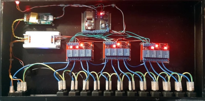
Because it is the power supply for a home automation system, each of the twelve outlets in this unit needed to be individually controllable. For that, three four-channel relay boards were used, each driven by an output on an ESP32. The ESP32 is running the Tasmota firmware to keep from having to reinvent the wheel, while MQTT was chosen as a protocol for controlling these outlets to allow for easy integration with the existing Node-RED-based home automation system. Not only is control built in to each channel, but the system can monitor the power consumption of each outlet individually as well. The entire system is housed in a custom-built sheet metal enclosure and painted to blend in well with any server rack.
Adding a system like this to a home automation system can simplify a lot of the design, and the scalable nature means that a system like this could easily be made much smaller or much larger without much additional effort. If you’d prefer to keep your hands away from mains voltage, though, we’ve seen similar builds based on USB power instead, with this one able to push around 2 kW.


“the power consumption of each outlet individually as well”
You misread your own source. It measures the total consumption, not each outlet. This is fairly obvious also from the header image.
Nice looking build and very neatly done. You may wish to put a fuse or circuit breaker on the input. I realize it’s probably on a protected circuit (15A or 20A breaker), but protecting your box would give some peace of mind.
It definitely needs a fuse. The C14 receptacle on the input is rated for 10A.
Replying to someones comment on the page, he mentioned that a 10A fuse is included in the main power socket.
The presence of the fuse is also obvious from the header image if you’re familiar with the terminal layout of AC inlets.
This contraption doesn’t comply with safety regulations. I doubt that the relay modules have adequate current carrying abilities and creepage distances. Switching only the neutral conductor is also frowned upon everywhere in the civilized world.
Creepage looks fine.
Switched neutral is bad, as is what looks like an ungrounded metal enclosure.
I have yet to see a chinese relay module that will pass regulations in a 230V country.
This. Why switch the neutral? And no obvious case earth on the metal box??
The colour of the wires is wrong. In his case (Italy), the wall sockets are not polarized, meaning that there is no way or knowing with certainty whether the live or neutral are where you expect them to be when you plug the device into the wall socket.
In other countries, you might find yourself wired between live and live with no neutral return.
The box should be bonded to Earth.
Even so, what if someone converts the thing and connects it directly to mains?
The colour rules exist for a reason. Switching just one line might also irritate residual current detection breakers.
Switching both lines would be perfect.
I’m more concerned with one wire from the mains source to all the outlets. If each of the switched outlets drew more than a few amps, the total draw can exceed the rating of that one wire. I’d get thicker wire if there’s a chance more than 1 will be switched on at a time
Agree that daisy chaining is a poor choice here, but if the mains fuse is 10A, that’s 16AWG. Can’t really tell, but the wiring looks lighter gauge than that.
Fusing and switching the neutral is definitely wrong though, and a PE (gnd) stud on the metal enclosure is an absolute must. I have to wonder if the designer messed up the color coding, because this seems like a rookie error.
To make this safe, while increasing the current, I’d use a 20A circuit (and fuse) on the input and design my own relay boards with brand name, UL/CE marked DPST relays rated for 15A to switch both sides of the mains. A dual row screw terminal strip would make splitting the input current simpler and allow a separate wire to each relay board. 14AWG wiring throughout, except 12AWG for the input connector, fuse, and the run to the terminal strip.
If this is 230V and fused 10A (which it should) than the wire should be 1.5mm2 – now the code in various European countries is more complicated – you will find extension cords intended for standard wall sockets (which are usually fused 16A) with 3x1mm2 wire and that is completely legal. (Great Britain is completely different though – they have their own thing – nowhere in Europe you will see circuits – maybe Malta)
Switching neutral though? That is a big NO NO. Metal box without connected earth – same thing. The creepage and stuff? That is more fire hazard than shock hazard – if you earth the box properly. There are no user accessible low voltage parts – you may as well treat this as if there is no isolated power supply at all.
Indeed. I bought some of these relay boards with “songle” brand relays, and opened one up. There is about two mm of clearance between the internal connection of the switch and the relay coil. These relays would never pass regulations for 230Vac use.
The PCB’s themselves are also designed badly. Clearance around the optocouplers is also very minimal. It should be 6mm for double insulated appliances, and 3mm for earthed equipment, but in general these modules have several tracks under the optocouplers.
If you want to have relays that are at least safe to use, then try some of the Omron G2R (clones?). They are not much more expensive, have a much nicer (narrower) form factor for most use cases, and at least they are safe to use. They even have a plastic labyrinth between the relay coil and the switches, so even if the relay contacts arc over, then it probably won’t reach the relay coil.
I suspect the “Omron G2R” you buy from Ali are just as fake as the Mitutoyo callipers. Longevity of the contacts may be reduced, but at least you still have the plastic labyrinth isolation and big creepage distances.
Have a look at the Omron G4A series, they have additional Faston tabs at the top which eliminate the need for screw terminals on the PCB.
I still would prefer 2 pole relays from a reputable source. More expensive, sure, but at least safe.
A DIN rail with some SSRs, a 5VDC power supply, and a maybe a GPIO expander on the Esp32 would be my choice. Built in optoisolation, easy to expand or repair, and all kinds of terminal blocks are readily available, including grounding blocks.
This is an incredibly dangerous box and should not be built or used in its current design.
Also the relays appear to switch the neutral which is totally the wrong thing to do. The photos also show a lot of missing Common connections so the relays won’t switch.
These relay boards are all right, but the relays are just cr*p. They stick, they do not switch cleanly, they spark and they are totally inconsistent in quality, meaning some will carry their specs, some will not. Use the boards, if you like, but replace the relays for some original Omrons or something. The quality difference between those generic chinesium relays and good ones is staggering.
Ok but why??? Also I wouldn’t trust chinese SW in ESP32
“Also I wouldn’t trust chinese SW in ESP32”
It isn’t, it’s Tasmota. Open Source, started by a dutch guy.
Yeah, no. Dont use those relays for 230v AC. I have, and it was not pretty and involved melting and smoke. In my experience, they are perfectly fine for low voltage, low amp DC setups/IOT/HomeAutomation but just dont use them for AC. Its not that much more expensive to get certified relays instead – and far safer.
How about using solid state relays.
this project has me shaking my head and saying simplicity is way better. anyways, i used to use X10 automation at my home and it was no end of problems and i got rid of it and don’t miss it at all. it was a solution in search of a problem, it turns out.
but when i threw it out, i took one of the switched outlet modules apart and i found this cool device. it was a stateful relay! you would give it a pulse and iirc some sort of solenoid would force a piece of plastic to rotate 90 degrees. when it was in one orientation, it was closed, and in the other, it was open. so it did not require coil current to maintain state.
too bad X10 was completely unusable as a signalling protocol…but i would still be inclined to avoid reinventing the wheel in this case. even if i built my own, i would definitely track down that magic relay. i just can’t shake the feeling that it will be one problem after another with this build and in a year he’ll *upgrade* to a department store power strip.
I agree with the above, having bought and tried several esp cheap relay boards from eBay and failed.
I ended up switching to the tplink outlet strips that let me control each outlet individually from HomeAssistant. Quality hardware, open source software, and far more compact than a dozen one-outlet switches.
As an engineer, I find the context of the article to be ambiguous. Is this powering a home automation system, or the circuits controlled by the home automation system? At 2kW, if the former, I’m appalled, as my Home Assistant runs on a RPi 4 , along with an integrated IoTaWatt that monitors 14 circuits and several integrated smartplugs that monitor the refrigerator, microwave, dishwasher, entertainment system, and laundry.
A demo of the type of system I have can be seen at https://demo.home-assistant.io/ . For those interested in monitoring energy consumption, make sure to click on the Energy lightningbolt icon on the left menu.
Back to this article, I fail to see the usefulness of such a system described herein, for if it is controlling circuits, then power to entire set of plugs and/or lights in rooms are either on or off, which would rarely fit the user stories of people seeking home automation.
Warning! I have had those little blue relays burn up over time in a similar setup switching AC. Mine was passing about 8A over a 12ga wire. Be extremely careful, don’t get even close to their amperage ratings, and if you smell anything weird a day or a week or 3 years into operation, address it immediately.