For an upcoming road trip, [Patrick] needed a small variable power supply. Instead of lugging around a bench supply, [Patrick] did the sensible thing and reverse engineered a cell phone charger to fit his requirements.
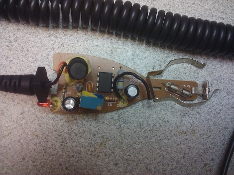
After cracking open an old Kyocera car charger, [Patrick] found a small PCB with completely labeled, all through-hole components – excellent reverse engineering potential. After finding an On Semi MC33063 IC, [Patrick] tore through the datasheets, generated a netlist, and developed a schematic that closely resembled the reference schematic given by the datasheets.
With all the grunt work done, [Patrick] set out to finish what he started – modifying the charger to output 3-10 Volts. After replacing a resistor with a 5k multiturn pot, [Patrick] was left with a power supply with a variable output from 2.8 to 8.8 Volts. Not exactly what was desired, but more than enough for the application at hand. While this hack isn’t a disco floor, it’s a great walkthough of the hacking process – building or modifying something to suit a need.


Not really groundbreaking but I think the most helpful thing is that the DC-DC converter is a switchmode one which can be quite handy if you want to put it into some kind of battery powered project where you don’t want to piss away the power by bleeding off the voltage with a linear regulator.
Nice writeup! I did a similar thing where I changed the resistor network on a charger intended for Apple products:
http://www.danreetz.com/blog/2011/01/25/de-apple-tize-your-usb-phone-charger/
Also, we have a couple people on my book scanner forums using these things to power Canon Powershot cameras.
Another tip – there are literally hundreds of chargers like these in dollar stores around the country. They have non-USB connectors on them, but you can get a whole switching DC-DC supply for a buck, and adjust it with one or two resistors. Watch out for the color coding on the wires though, the wire colors are often reversed with red being negative and black being positive.
done this before, its handy for when you need a power supply in a pinch. walmart sells decent ones for $5. instead of replacing one resistor i replaced the resistor divider at the output with a potentiometer.
Be careful of the dollar store chargers. some a linear discrete designs. I usually use ones from the phone carriers and get them at yard sales or thrift stores. About 90% of them use the Onsemi part or a second source. Some will even have a tag hanging on the cord saying “intelligent charger 33063” Most will be set for 5V to supply the actual charging circuit in the phone for the Li-ion battery. Some will have un-used component locations for actual charge control circuitry.
Some have an empty part labeled “C” and a wirejumper labeled “L” and produce lots of radio frequency interference. I’ve got one like that, plus some other cheap electronics from China that’s been part-reduced to save pennies and create noise.
Simple but effective.
Nice write-up, and good job.
I’ve modified a few “brick” style switching AC to DC converters similarly. Although they’re more complex, finding the right resistor to modify is usually easy and can be done in a few minutes; even without any reverse engineering. Just attach a 100k resistor to a couple of probes. Use the probes to connect your resistor in parallel to a resistor on the board you think might control the voltage. If you guess wrong, the current through 100k is small enough not to harm anything (at least in my experience). If you guess right, the output voltage will change slightly (usually a few millivolts).
Also useful, there’s a compact switching regulator module (KIS-3R33S) which is currently available for less than a dollar from Satistronics and Ebay. It takes 5-23V in, and outputs 3.3V @ 3A. With a similar bit of modification (usually documented by the seller), it can output other voltages. They’re so handy, I just bought 20 of them to stock my parts box for future projects.
The empty “C” and the jumper “L” on the ones that produce lots of noise (both radiated and on the supply) are probably the equivalent of C3 and L1, respectively, on the schematic given: they are part of the output filter. If you end up with one of these and need to decrease your output noise, add a (large-ish) electrolytic at C. If you can, an inductor at L would be ideal – if not, a wire-wound or spiral-cut small-value resistor can be substituted. Either way, the key on the output is filtration. Especially as that is part of your regulation feedback.
Sparkfun has some 7.5v 1A ones for sale for $0.95 (350+in stock as I write this) http://www.sparkfun.com/products/8835/ It also has a DC-DC converter, but I couldn’t find a datasheet worth a damn…
If you are more interrested in the chip Dave made a blogpost of it: http://www.eevblog.com/2010/09/10/eevblog-110-lets-design-a-dc-to-dc-switchmode-converter/