If you’ve run out of I/O pins on a project and need a way to add user input you can find a slew of port expanders that work with various communications protocols like I2C and 1-Wire. But if you just want to add in some buttons without reaching for an extra IC you’ll love this hack. [John Boxall] shows how to add four buttons using one ADC pin.
The concept is nothing new. The buttons make up an R2R resistive ladder. When one of them is pressed, it completes the circuit for a voltage divider. The results are measured by the analog-to-digital converter of an IC to tell which button was pressed. The difficult part is calculating the resistor values. [John] is using eight resistors made up of just two different values. Every button and every combination of buttons has a unique voltage result which can be discerned by the chip. He even made a truth table so you don’t have to.
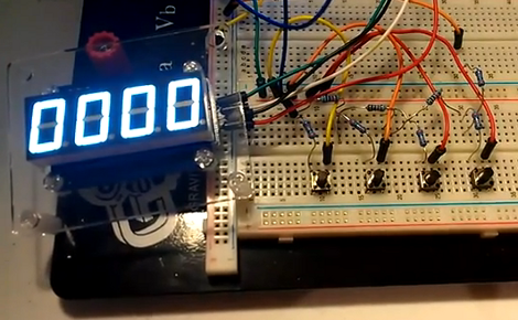
The example circuit seen in the video after the break uses an Arduino. But this concept is directly applicable to any microcontroller. And it should be quite easy to use an ADC interrupt to drive all of the button-read events.[youtube=http://www.youtube.com/watch?v=BZ49TgZkUW8&w=470]


This site is unbelievable!!! That’s amazing!!! How many projects with arduino!! Thanks!!!
So many of these hacks are straight from decades old application notes. This one is from 1989 Microchip tips and tricks.
Not trying to be negative. Just saying if you like this sort of thing, look into manufacturer’s app notes. Really really creative helpful stuff there.
Some of the best are linear’s old ones, microchip and Maxim.
same concept Balupluct use on the car stereos for wired control. a resistor ladder so it was easy to wire up the landrover dashboard radio controls. to my new car radio
Blaupunkt uses this for stereos? Wouldn’t they have the resources to just use chips with enough pins?
Resources are something you need in your own R&D. For a product you need maximum profit, and since the price people are willing to pay is fixed it means you need to minimise cost.
Same thing with hardware debouncers. There’s plenty on the market, you can make them easily with an RC filter, but I have yet to see a consumer product make use of anything other than software debouncing.
When dealing with volume production, I often hear the engineers say “but how many pennies”
for example, when a resistor cost you 0.00152 each in bulk,and the difference tween two micro controllers is about 61 cents, and you make a batch of 100,000 units (which is not high but not low) and have 4 switches but 1 pin…
(((0.00152*4)* 100,000)+(1.07 * 100,000))= 107,608$
vs (1.68*100000)= 168,000$ .. you just saved 60,392$
now think of it in Bosch’s orders where 100,000 is a single regional distributor’s order over 2-3 quarters, globally?
OMG why am i not on this site yet lol
Ive done this so long ago:
http://atomsofttech.com/downloads/JPUG/
Mines also uses “just basic” for finding Resistor values for larger keypads.
“The difficult part is calculating the resistor values”
Not *that* difficult:
https://en.wikipedia.org/wiki/Resistor_ladder
You know ….. this is one of those “why the hell didn’t I think of that” projects, that manages to both amaze and humble.
Hmmm, Time to rethink using the ADC as general IO on my ATTiny projects. Suddenly Buttons!
Just remember how many clock cycles it takes to read the analog pin. And the downside is not being able to read button presses inside an interupt as easily (UI purposes).
Ive been thinking about doing this too, with an ATTiny85 project that needs more IO since one of it’s pins can just flip into 10-bit ADC mode (with an internal reference, so it only takes 1 pin), I figure I can probably get 4 or 5 inputs out of it without loosing precision. Means I can actually hook for or 5 (S)NES controllers to my USB port with V-USB. ;-)
The first time I ran into a circuit like this was in a panasonic cd player the buttons had quit working so after some investigation it was instead controlled by resistors in a project box w/ switches and a headphone jack to the orginal connections.
First saw this in an old panasonic portable cd-player back in the late 90’s
I took a reliability class from an engineer at one of the “big 3” Detroit carmakers. When someone brought up this sort of multiplexing method, he visibly shuddered. His first reccomendation was to not do it, and if you must, no more than 3 switches. Implementing this sort of control scheme is pretty difficult to do right/reliably. Be very careful in your analysis and in your research on the switches you use- as they wear, the resistance will vary, and the ADC output will very definitely be affected.
“Be very careful in your analysis and in your research on the switches you use- as they wear, the resistance will vary, and the ADC output will very definitely be affected.”
Couldn’t you get around that by using transistors that are triggered by the button press? That way you are effectively removing the button and possible wear from the equation… I believe.
This sounds just about right… Problem fixed :) (i think)
Transistors do remove some of the effect of the swiches (by a factor of the beta of the transistor, I think), but doesn’t eliminate it. You also have the variability of the transistors over temperature (a PN junction also works as a good temperature sensor), and the variability of the resistors- looking at the chart in TFA, the difference between 2 different sets of keypresses can be a lot smaller than 1%… I can’t remember the dependence that an R2R ladder gives you with 1% resistors, but I don’t think that the ultimate accuracy is better than 1%. On the other hand this circuit should work well on one circuit at one particular temperature, though it will probably require tweaking on each individual incarnation of the circuit.
It’s quite common in the automotive industry for steering wheel controls.
My Honda Accord has resistor ladder switches for the 4 radio buttons and another set for 4 navigation system buttons.
I *think* the 4 cruise control buttons are another resistor ladder set too.
and yes, I know this is a 6 year old thread.
Cool. I found the same hack/trick in a cheap USB microscope: https://hackaday.com/2017/06/26/hacking-an-inspection-microscope/
I guess it’s a sign that ADCs are cheaper than shift registers these days?
The Parallax Basic Stamp book has had example code to do this for at least 15 years.
Nice.
The Lego NXT uses the same trick for its buttons.
I was disappointment that they didn’t use smaller values to shift all the analog values into the logic ‘0’ threshold. It’s probably hard to do for 4 buttons.
But I’ve done it with 2, that way you get an interrupt signaling you have a button press. Then in your ISR you do an analog conversion. This approach also acts as debouching filter.
It is sad that so many have not realized that this is EXACTLY how the Arduino LCD & BUTTON Shield works!!!
ample circuit diagrams and code already provided in the Arduino library
One of my favorite little hacks. I’ve used in a few projects for 3 buttons, and it’s very easy to do using only 4 resistors: a single 10K pull up and then 3 parallels of a resistor and a button in series, with resistors 10K, 22K, 47K (one value doubling the previous). You can read any button combination.
Saw this hack for the first time when I took apart a chinese mp4 player :)
why use a ladder? for arduino stick them on a analog pin and fire up the internal pull up resistor on the atmega. wire the other side in a chain of resistors which then connect to ground
B B B B
| | | |
|r1-r2-r3-gnd
no math,half the parts, works the same
Thought I’d share an odd way I’ve seen this used.
Not long ago, I was troubleshooting a remote control that sometimes transmitted the wrong code. I soon found two weird things:
1) Some of the traces to the key contacts were in copper. Others were silkscreened in with carbon conductive ink, for no immediately apparent reason.
2) The keys were matrixed, but I noticed that several keys closed the *same* row and column. And there were fewer MCU pins being used than should be required for a keypad of this size.
After some head-scratching, I figured out it was reading the matrix via analog inputs. And using the resistance of the different lengths of conductive ink traces to differentiate between several buttons on the same row/column combo!
Clever. But not very reliable. The conductive ink’s resistance had apparently grown higher over time, causing the problem. Placing a few dabs of new ink on the problematic traces lowered the resistance enough to get it working again, though I’m not sure for how long.
that little trick, the R2R ladder, as well as some other equally cool and usefull ones are listed here in Microchips Tips & Tricks for 8 pin PIC devices, which has a TON of crossover to arduino based things obviously. A very short and concise and AWESOME reference, I found it recently, only been playing w/ arduino a few months now, and it really pushed my project forward FAST.
MICROCHIP Tips & Tricks [www.microchip.com]
also a much longer read but full of things I have yet to read, another old paper by microchip:
Compiled tips and tricks [microchip.com]
it is amazing what they pull off with only 8 pins
Car makers have used this hack for steering wheel mounted buttons, i.e. cruise control, climate control, stereo control, etc., for a long time. It means only one pair of wires needs one clock spring to bridge from the dash to the rotating wheel.
In fact it can be done with a DIGITAL I/O pin!!.
The capacitor is connected to the power source with a Known resistor, and the capacitor to the I/O pin (configured as input). When the Input pin “feels” a logic “1” (see datasheet for the exact voltage for logic 1) . stop timer and make calculations. Next, configures de pin as OUT and put logic 0. This discharges de capacitor, timer is cleared, pin again as input, and the cicle starts again.
The time measured is a function of the resistor (variable) and the voltage and capacitance (Fixed).
If you make r-2r ladder with swithces and resistor, you have an multiplexed digital input just using one single digital i/o pin!!. Of course it’s a bit slow (useles for encoder , fast sensors, etc), but very, very useful for User Interface buttons (Humans are very slow!!)
I agree with some people, that kind of “hacks” are 10 years or more old!!
There is a method using RC charge time measurement using a digital pin and a timer. Yo can maque an r-2r ladder with switches that change the R of the RC circuit!!
Ha! You beat me to it. I was just going to point that out.
I have been doing this since 1976. Resistor ladder on a digital pin with a capacitor. Depending on the chip and the values, you don’t even need the cap if it is a one unit design and you can count on the internal capacitance not changing. Or if there is a way to autocalibrate in software.
It’s certainly not a new idea, but it is a good one for everyone to have in their toolkit.
A lot of ham radios use the ladder method to communicate band information between the radio and a tuner or amplifier.
Peter
Hey you visited Colombia some time ago!, but missed Cali!
link ” how to add four buttons using one ADC pin.” quoted in main text: http://blog.littlebirdelectronics.com/tutorial-analog-input-for-multiple-buttons-pa
is broken