Unlike the CRTs found in big old televisions, vector displays are a bit of a historical oddity. Instead of sweeping an electron beam across the screen from left to right and top to bottom, a vector display draws lines between two points on a screen. Once used in arcade games such as Asteroids, Tempest, and old FAA displays, vector monitors have fallen out of favor due to either the complexity or difficulty in acquiring the needed CRT. The folks over at NYC Resistor put up a great tutorial for getting a vector display up and running, and even managed to put a clock on an oscilloscope.
The key component of getting a vector display to work is the digital to analog converter. This DAC takes voltages from eight pins on a Teensy 2.0 dev board and converts them to a voltage anywhere in between 0 and 5 Volts. After connecting the output of this DAC to an input on an oscilloscope, the microcontroller can draw a line between any two points on an axis.
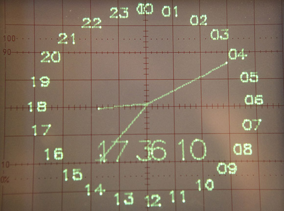
In the video after the break, you can see two of these DACs connected to an oscilloscope displaying a clock. It’s a very cool piece of work, and something that finally gives a purpose to the ancient CRT oscilloscope you might have lying around.
[flickr video=7925036218]


I thought vector displays would give you smooth diagonal lines and smooth round shapes, not the aliased broken lines typical of CRT scanning. Am I missing something?
The algorithm they are using generates a raster 256×256 gird of dots…so yeah although its not scanning the entire area it is NOT vector
I’m guessing that the display could manage smooth diagonals and curves but you’re seeing the steps from the DAC.
Almost all Scope clocks are based on DAC’s and is jagged to look at. IMO the only way to do it right is like David does it: http://www.cathodecorner.com/sc100.html
If you want smooth lines you could have the DACs output beam speed into integrating op-amps when the beam’s on and set the position when it’s off.
Depends how you drive it. As the original article states, there’s just not enough parts in their source to get the knife-edge straight lines and smooth rounded curves that vector displays are known for.
So they’re pixelizing the image and painting a collection of points instead of building up their source into a proper vector source. Which proves they can paint an image on the ‘scope and gives them somewhere to go from here.
It’s all in the dynamics. The intensity of the beam is proportional to how long it stays at any particular location. The brighter dots at the vertices indicate that the software is taking a while to reload the DACs. It’s all a trade-off between number of points drawn and refresh time.
I recall (but not where!) readinga website about the early Atari vector games being developed. The very early ones used a DAC straight to CRT like this. But later games, mighta been Asteroids, used the integrating op-amp method. As you say, getting the beam to move at a constant rate, for constant brightness, however long the line, was a big problem. It looked like it was hell to solve, but they managed it.
The site I saw it on had the old circuit diagrams, so it’s possible, if not easy. Dunno if you could crib Atari’s maths or if you’d need to work it out again, but it does look oh so very good to see crisp infinitely-smooth vectory vectors.
Yes, this is a quasi-vector. In what may be considered as ‘true vector’ you only send the line’s end-points to the scope and the scope “draws” the whole line. It is less memory intensive, but for true vector the time between end-points varies with line length. Getting smooth lines *is* fairly easy. Because the CRT is fast enough to follow the DAC, you see what the DACs put out; steps and all. You need something after the DACs to slow the signal down. By putting some kind of a low pass filter after the DACs you effectively slow the scope down so it can’t follow the DACs and thus removes the steps. There are several ways to do this. Quite good results can be obtained by a simple RC low pass filter when doing it like this where the DACs always put out very short line segments. Since an RC gives an exponential response, using this to make long lines makes the start dimmer than the end. The suggested “integrating OpAmp” can give a constant speed of the beam across the screen and therefore a constant brightness, but required timing proportional to line length.
I do laser light shows and designed a scanner simulator for a scope that more closely approximates the response of my mechanical scanners. These have quite a high order response that starts slow, builds to a constant speed, then comes to a gradual stop. I used a third order filtering consisting of a two pole Sallen-Key low pass followed by an RC. This gives a quite uniform brightness.
I haven’t fully analyzed Dave’s Scope Clock (Cathode Corner referenced above), but he also puts out short segments, but describes generating circular arcs with sine and cosine signals and appears to have low pass and band pass filters tuned to the sine and cosine frequencies (U15 on schematic pg 3), so all the signal distortion is filtered out (in the frequency domain, so to speak) thus removing all steps very nicely, from his pictures.
Regards, Steve N.
P.S.
I should add that there are many examoles of this on Youtube and I don’t hink any of them use some “anti-jaggy” filtering. Some may be doing things so fat that they just have an inherent bandwith limit in the circuitry that they are pushing which also attenuates the harminic distortion products.
Steve
CRT ‘scopes are ancient and lying around? Who knew?
A combination of vector & CRT is still used today: the displays in most commercial airliner cockpits. Lines and characters/symbols are drawn as a vector combined with a raster fill for the shaded areas. Only in the last few years they are replaced with LCD-screens in new build aircraft.
Just because Ingress wasn’t enough of a thing already, I got bored and displayed the logo on a Vectrex. There’s a great vector display based platform everyone seems to forget.
https://plus.google.com/109504560021053946833/posts/jaFVjCgv4fd
There’s a pretty good technical explanation of XY monitors (as they’re otherwise known) at http://www.jmargolin.com/xy/xymon.htm although if you want the real nitty gritty I recommend looking at some of the great repair videos made by Randy Fromm. His explanations of how to repair CRTs is probably the clearest set of videos I’ve ever seen explaining how they actually work. It’ll take you 5-6 hours to view them all, but you won’t regret it. http://www.youtube.com/user/randyfromm?feature=watch
The set of monitor videos you want to watch begin quite a way down the page at http://www.youtube.com/watch?v=YsZ5PJB-w2s – the first of the first listed series of CRT videos cuts off abruptly after half an hour or so.
I was going to link to Jed Margolin’s site as well. His vector generator article may be more applicable to this topic: http://www.jmargolin.com/vgens/vgens.htm
An old Atari employee, he has some other articles worth reading that go behind the scenes of some classic Atari games such as Asteroids and Battlezone… http://www.jmargolin.com/
The problem is actually finding a working XY. I love LCD, I really do, but it pisses me off when the government passes a law banning CRT’s beyond 25″. Nevermind getting screwed with aspect ratio choices.
Some people are resorting to hoarding raster tubes and rebuilding them.
I love how my PS3 and 360 look on my AQUOS but Tempest is and always will be my favorite white elephant.
Raster CRTs can be used as vector tubes. It won’t be as sharp as a monochrome tube without a shadow mask, but you can make full colour vector graphics.
What do you mean “finally puts a use to”? I still use my Philips analogue oscope on a regular basis. They don’t do the fancy stuff a digital scope can, but they’re cheaper and more flexible, as this hack shows.
Analog oscilloscopes were (almost?) all based on CRTs with the displays drawn with vectors. They aren’t difficult to find in junk electronics shops, Craigslist, eBay, etc (although the shipping costs will kill you!) and can often be gotten for free by finding an electronics enthusiast over the age of 40 who’s a pack rat.
Another user of vector driven displays were military aircraft, before the introduction of glass cockpits. The original space shuttle displays were a trio of vector displays – really sophisticated for 1970s technology, but hopelessly outdated by the 1990s. Starting in 2001 glass cockpit displays by Honeywell were introduced in the shuttle fleet. I was one of under a dozen reporters to get invited inside Atlantis for a demonstration of the new displays – tres impressive even though I had seen and fooled around with the prototypes many times before.