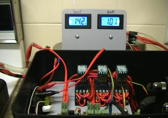
This is the control and monitoring hardware which [Jack] built for his campfire electricity generator. He’s done an amazing job to get this far. You can see he’s pulling 1 Amp at 14.2 Volts off of the system. But there one gotcha that’s still plaguing him.
The rig uses a big metal plate as a heat sink over the campfire (which is simulated by a cooking stove for testing). On the back of that plate is an array of Peltier coolers which generate electricity based on the temperature difference from one side to the other — it’s the same theory behind candle generators. The cold side has a heat sink with water running through it. What you see above are three relays which switch between using the Peltiers in series or in parallel based on their voltage output. You can’t really make it out there but there’s a radiator and recirculating pump to the right which are used to cool the water. The gotcha we mentioned is that the radiator can’t quite keep up with the heat of the fire. To get the results seen above [Jack] is running cold water from the tap through the radiator. But maybe if this were used in the winter the water could be circulated through a big box full of snow. Just keep shoveling it in to keep up the electrical potential!
After the break we’ve embedded part four of the project video as it shows off the array of peltier coolers quite well. You will also see part five (radiator and recirculating pump testing) from which this image was taken.
Part four – electric stove testing
http://www.youtube.com/watch?v=zjfrHgbSHaU
Part five – radiator and recirculation pump testing


I love it. I’ve done something similar with a peltier cooler to charge a cell phone. But I never followed that project through to completion. This seems fairly well executed.
Hello sir, Iam an student conduct similar project as you mentioned ( to charge a cell phone using LTC3105) , but Iam getting an output of 1.8v with the input of 300mv . The output expected was around 5v , ltc3105 says output can be adjusted frm 1.6 to 5.25v ! if u can suggest me it would surely help me out !
Using latching relays or mosfets would reduce the power currently used by the relays.
20mA at around 13volts, multiplied by three relays, is almost a watt – enough to charge a phone!
Either use a larger radiator or do a passive cooling setup.
How exactly would passive cooling keep up to the heat of a fire ??
Although cool, might a steam turbine on top of the fire running a small dc motor be more efficient?
That was exactly my thought. I can think of a number of alternate ideas better suited to powering small electrical devices. Not quite as many I would want to carry on my back in the wild. So to that, I missed something, what is his goal with this project? What’s he trying to run/charge?
Yeah….I just checked an efficiency chart…not sure about the validity…but peltiers are only like 5% efficient….for use as heat pumps…compressors are like 50% (ten times better)….I am gonna have to guess that it is not too efficient…but off the grid somewhere…it is more portable than a steam engine…and could charge stuff up…even at night as long as you have a fire….would be interesting to use in a geothermal vent…or some hot springs place…but there are solar panels out putting 16V @ 35Watts close to the size as that thing…a full 50x100cm is doing about 16V @ 70Watts…
I’m not complaining, though….it is a great project for discovery learning plus you can use it when your done! I wonder how much peltiers are per cm squared….high cost? heck you could use them on radiators and other things that can be passively cooled to recover some percent of energy lost through heat……
4x4cm 150 watt (input power, not generation output) peltiers are on ebay for about $7 each. there are much better ones that are 6.2×6.2cm and are upwards of 400 watts input but $40+
they last forever if used properly and at those prices most people can afford to give a thermoelectric project a try.
have teh water for the turbine cool the peltior! call it a hybrid!
You were so close… and yet so far. Boiling the water takes away the heat without needing the radiator. So you have the peltiers stuck to the bottom of a saucepan with a thick copper base. You have water in the pan. You stick the pan on the fire.
The peltier elements will have to cope with 100C to 130C approx working temperature, but that’s no biggy.
Solution: insulate the hot side to moderate the amount of heat flowing through the peltiers. This can be done with something like, a small air gap between two metal plates.
The temperature on either side of the material can be throught of as voltage, heat flow as current, and the insulating properties of the material like the electrical resistance in a circuit. Each piece of material in the path has its own resistance. Now the system can be thought of in terms of the Ohm’s law, and it can be modeled and computed as such.
The fundamental problem is that the peltiers have thermal resistance in and of themselves, so the temperature is going to rise anyways no matter how well you cool the cold side. If you have a campfire on the hot side, it’s like trying to regulate down the voltage of a car battery to a couple hundred millivolts by shorting it through your load. If the load has some resistance, it just won’t happen.
Love it. Love the design mostly as it looks like something you would see on a submarine or something. Easy to see and follow circuits, which is handy when you’re cranking that much juice :) Great job and hope the best on your future builds!
You’ll just have to find camp with river or lake at least…
Wow. I know people that cut the borders off their maps to save a few tenths of a gram, cut their toothbrushes in half….. Good luck carrying this thing with ya out there!
Just don’t put the elements IN the fire! Seriously, just move it away from the fire some when it’s that hot.
if the fire is that hot wouldn’t thermocouples be a better idea?
This uses thermocouples. A Peltier generator is a generator that uses the thermocouple effect. It just has a name slapped onto it.
Actually it’s the Seebeck effect (reverse Peltier)
No, that’s the Reitlep effect.
Good grief…. :-)
There are already special charging pans out there. They have a peltier in them and can charge a phone while boiling water. My point isn’t that he should buy rather than build but rather that it CAN be done without any flowing water. The water will only ever get to X temperature while the fire side should always be higher.
See this video for two commercial options – http://www.youtube.com/watch?v=58b8Acjwtl4
perhaps instead of a fan and radiator just pump it into a large capacity bucket. They make nice flexible 5 gallon buckets for camping that pack small, could also work well if you used the hot water from the Device to heat your shower…….
Heatpipes? Seems like an application for one of those If i ever saw one!
Just camp by a stream and use that for cooling. :)
Yes, insulation and efficiency are the issues with peltiers. Mostly useful in tight spaces where a better option won’t fit.
as said before, but put the unit on some large found stones, and then place them near the fire… you can control the heat by the distance to the fire.
So, the pump he uses to circulate the cooling water isn’t quite sufficient to keep up, right? Still that pump uses a lot more power than the peltiers generate.
It would be more efficient to just scrap the whole thing and power his appliance directly from mains. In fact, that would actually reduce the amount of power drawn from mains.. ;)
I wonder how much this thing weighs, just to compare with carrying batteries…
You don’t want to put the thermal plate directly on the heat of the fire. For a campfire device you want to use a heat-pump, a copper rod (.5″ x 8″-12″) exposed to the heat (camp fire) and attached (soldered) to your generator plate to transfer and spread the heat should deliver a better quality of heat without creating the overheating issue on the generator side. You should be able to then use heat-sinks and a small fan to hold the temperature difference rather than the water system. This is a very fun project and can be scaled up nicely. Nice design too.
I think that it’s simply too small a water volume. Needs a large “header” tank, and a larger surface area for cooling. It doesn’t need to be a closed system.
Look at the size of the cooling water tanks for old stationary enginess etc.
using thermosyphon with a big tank should avoid the need of an electrical pump
Dude, I wish my projects were all made with that level of craftsmanship.
Hot side getting too hot, and then the cool side is above the hot side, further taking on heat due to the fact that heat rises? Seems more logical to bury the cold side in the earth, using convection pipes as necessary, and then build the fire on top of the upward facing hot-side, possibly using a ceramic plate or something else as a slight insulator to keep the hot coals from directly contacting the hot side.
Just a thought…
There is a company who makes allready use of the peltier slabs.
http://housewares.about.com/od/heatingwithwood/gr/ecofan.htm
I tryed to make one for my woodstove, not yet ready.
For some reason my meter’s just shit itself ;-)
if we could only come up with av way to run frion while still maintaining enough power to run something else
have you tried maybe a co2 system on the cold side?
I’m looking up stuff about the peltier’s,one of the things is that they are talking about the max. temp. difference of it,if you stay in that zone you get the max out of it.Going higher does not work. Dax says to leave a gap (insulate)between the two sides,totally agree with that.If you would make the aluminum plate on the cold side thicker,or box it to have more cooling on the surface.When you keep it a closed circuit u can use glicol coolant,but you will need a lot of surface,ore dip the radiator in a reservoir.Also when you tilt your generator you will still heat the peltier’s by the radiation flow(heat travels up) and probably put less heat in the total divice.I hope you have some use of my pondering
The surface area issue. Think about a heatsink it folds over and over
or has a complex 3d structure to maximize surface area in a give space
for the purpose of distributing heat. The efficiency of “pelters” is a measure
of thermal difference that the cooler can operate at. If a natural condition
can provide a large temperature swing have at it.
I think the more salient point is, this is a decent way to utilize
more of the energy being consumed and essentially wasted.
Free work energy, only in that you already accepted huge lossy systems
in the first place.
You already have the fire going, because you needed the fire, you didn’t build
the fire with the purpose of electricity.
I want to hook up a steam turbine to my apartments radiator springs nice that is a fee utility… Haha where can I buy one that would word with a typical in home radiator?
just my two bits here: to drop the power loss from using the relay setup for switching between serial/parallel voltage from the Peltier-elements, just connect at buck/boost converter to the Peltiers – it’ll cost about 5-10$ for a unit capable of supplying a constant output voltage of e.g. 14.4V (lead-acid battery safe charge level) at an input from appx. 5-20V and the demonstrated 1A current.
Efficiency for such a gadget is typically >95%.
If looking at this solution, make sure you check out combined buck/boost converters, and not just buck (down-adjusting) or just boost (up-adjustning converters.
Still, there’s a potential loss of up to 5%, and this may be cut down even more, by sticking to the principle of switching between serial/parallel on the Peltier-elements, but swapping the relays for a solid-state solution. Solid-state relays (SSRs) are quite cheap today (specially on China market), and given the lack of mechanical operation, there’s both some energy to save, as well as some long term stability to gain.
The choice between the two solutions depends on what you are going to use your energy for – in the real world, I would put my money on the buck/boost converter solution, as it will be the generally most efficient setup for driving appliances and charging batteries.
But anyhow and whatever; – even though I’ve played with Peltier elements on and of over the past 10-15 years, I’ve just become aware of this reverse principle today, and I just wanted to express my admiration for the people who really check out the outer bounds of green energy.
Sorry to continue my stray thougts on the subject, but I’m a bit bored today ;-)
When it comes to the physical construction of the generator, I see it as this (assuming we’re still talking camp fire):
1. “harvesting” the heat is easy, and a reasonable alu-plate for this purpose doesn’t weigh much.
2. “dumping” the spill-heat from the warm side is quite another thing: first of all, even if we insulate the gap between the two sides of the Peltier heat/cool sinks optimally, the cooling sing will still be close to the hot environment of the camp-fire, and unless we build our fire in a windy spot (and would we?), this will be counterproductive.
So, – to suggest a solution: lets move the surpluss heat away from the area, and dispose of the heat a metre or two away (3-6 feet).
This could possibly be achieved by using a vaporisor with a passive condenser . . .
The vaporisor could be implemented with a small alu-chamber of the types used to cool computer-processors (you coud check this one out (don’t let the word “thermoelectric” fool you – it’s lust a hollow block of alu ;-): http://eud.dx.com/product/aluminum-water-block-thermoelectric-cooling-module-silver-844173740#.VUfnXCe1Gko ).
If we had a small container with e.g. pure alcohol in it (great for camping too, if the experiment fails ;-), and it was connected to the above mentioned alu-block, then the alcohol would vaporize in the block.
Given that we had inserted a few one-way valves and placed the container with the alcohol some feet way – and the whole system was connected in a ring/feed-back fashion – then the alcohol would vaporize in the alu-block, the alu-block would suck in some liquid alcohol, the vapors would condense in the remote container, and so on … have you ever seen those small tin-boats that sails because you put a small dry-spirit (grill-starter?) tablet in them ? That’s the principle we would go for.
Anyhow, the benefit here is, that we move the heat away to a colder spot, and the greater the temp. diff., the easier we can dissipate the energy.
Intuitively I would estimate that these components would be several times as efficient as a passive cooling sink connected directly to the Peltier-element, if we’re comparing the weight of the camping equipment.
And don’t forget: if the experiment fails, there’s always the alcohol to comfort you! ;-)
My thought would be to use aluminum block Heat exchangers to the heat side of the Peltzer run Steam from a small pressure cooker 2 quart through the Heat exchangers this way the heat never gets over 212° or not much over that depending on the superheat then there would be another heat sink on the cool side of the Peltzer where a steam turbine would run a fan over the heat sink this way you’re not using any of you electrical energy generated to run a fan or pump or anything else
Cool project, great comments, I am considering investing in a DIY home TEG mounted directly to the side of a few thousand gallon solar heat bank at ~140° and cooled by a heat pipe into the earth instead of PV panels, it would esentialy be a solar charged water battery, now it looks wise to mount the generator away from the heat source and selectivly pipe the heat to it through some sort of adjustable mechanical means such as a insulated door or sliding a rod in tube heat pipe, witch brings me to my recommendation for the OP’s use case, a aluminum tube dubbling as a walking stick closed and tapered at the bottom, neoprene insulated grip from midway up, the top of the tube would be caped with the generator on the end or side with a fancy looking circular radiator and a USB port, make LED indicators for over heated and add heat states or for extra points report usage through USB to a app, I would personaly just use a thin solar film generator and a small USB portable power pack if I ever spent more than a day or two at a time, power to the peaceful.
7km long deep closed cylinder with peltier walls and water inside, also little turbogenerators for steam inside could give 1GWt as permanent energy source, go for it
But hang-on, I saw a campfire that can charge your phone. Has 1amp USB ports.
Doesn’t it also use peltiers?