Headphone amplifiers make for simple, practical electronics projects. The Bass Bump Headphone Amp is no exception, since it’s made out of easy to source parts, and can be built on a proto-board.
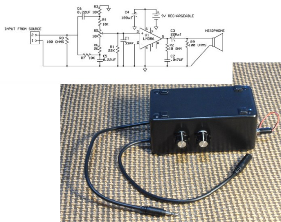
We’ve seen many variants of the classic cMoy amplifier, including this pretty one. The Bass Bump differs by providing control over bass frequencies. It does this by putting a filter in front of the amplifier, with a potentiometer to select the mix of frequencies. This goes into a LM386 audio amplifier. At the output is a Zobel network to keep the impedance low at high frequencies. The amplifier can be powered from either a 9V rechargeable battery, or a USB port.
It’s a simple build, but definitely a good one to try on a rainy day. The write up explains how the analog circuitry works, and gives you full instructions on how to build it. After the break, check out a video overview of the project.


But LM386 is not that “hi-fi” … It’s easy to make a much higher quality with a better opamp + 2 transistors.
I get that it is educational…but why should it be bad?
It’s probably good enough for someone who wants to pump more bass into their headphones. Tone control is outside the HiFi league anyway, IMO.
It’s better than what is coming out of any android phone or iphone. Honestly, “hifi” only matters when your source audio and headphones are not garbage. I dont see many of you walking around with decent headphones, just those garbage earbuds that sound like crud, but then none of you are listening to music that is not mastered by a moron and the had all the soul crushed out of it then converted to a lossy format pushed through a 0.05 audio subsystem.
An LM386 is a step up from what most people have already.
I see that rumors of your demise were greatly exaggerated.
Sorry but all audio mastering guys are morons. They crush the soul out of it with the loudness BS they all are guilty of.
Way to broadly generalize all members of a whole trade. I know a few mastering engineers, all of whom are personally opposed to the loudness war crap, and basically just do it because their bosses/clients tell them to.
I highly doubt it is better than *ANY* phone. Some have quite good quality output, you should check some tests. Of course, it depends on the file quality as well.
I tried building a headphone amp once, or twice, never got them to work all that well. I’m convinced that analog circuits are witch craft. I’ll stick to the cold dead world of digital, at least that makes sense to me.
Man what a bad choice for a chip. A modern Class-D device would be much more efficient and less noisy. Then there’s selective input network – quite lossy. But by tying a cap to one of the 386’s pins (can’t remember which) you can almost double the gain.
One of my first circuits was an LM386. Pins 1 and 8 for Gain, and pins 1 and 5 for Bass.
For what it’s worth the front end tone control used here is basically a simple but effective “Big Muff” type. (see Duncan’s freeware Tone Stack Calculator ).
All tone controls by their nature have “insertion loss”, typically around -20dB, and obtain “boost” by providing less loss since there is no way of obtaining gain from a passive circuit. The “Big Muff” control has an insertion loss of only about -10dB set flat but falls to 0dB for full treble boost meaning that overall this circuit is capable of +26dB over the source. Since this is obviously intended to be driven by the power amplifier in an MP3 player or the like the available gain should be more than sufficient – somewhat excessive if anything.
Arrangements to further increase the voltage gain of the LM386 do so by reducing its very considerable negative feedback and therefore also increase the basic noise and distortion, something the datasheet is coy about.
While the LM386 is not Hi-Fi, with a THD of less than 0.5% (~0.2%) and power output of 500-700mW this is a very typical application for which it is normally quite sufficient. Limited power into headphones, and particularly into earbuds, is a good thing if you value your hearing – seriously.
Unlike a Class-D amplifier this only requires the normal Zobel network and no post filter that would have increased the component count and complexity for no real advantage. The author explains the reasons for his choice, and as he says, “The LM386 performs well and keeps things simple.”
Thanks, AussieTech. You covered every point I was going to make in response.
I would also state that digital amplifiers are not trivial to implement. They’re way above the skill level of a DIP-8 analog chip. Of course there are opamps with better THD+N specs than the LM386 but when you start looking into current delivery into 8 or 16 Ohms they fall on their faces. I know because I tested a ton of them when developing this. People hate on the 386 because it’s primitive and doesn’t have pretty specs but in real world applications it gets the job done.
Cheers!
As an ex-RS manager, I think it’s great that they are now doing these projects. I was on the national council for them and was always advocating this type of advertising as well as adding more automation/robotics items (steppers and servos) to their in store offerings… I may have to swing into my old store and see what’s new!
They don’t carry the variety of parts I’d like access to: I still find myself ordering from China half the time. They used to have a much larger inventory back in the old days.
The RS website has a pretty deep online-only catalog. Far more than what’s stocked in the stores. And their shipping is fast. My last order from Shenzhen took 34 days to arrive. I ordered the parts for this amp from RS on a Monday morning and they were delivered that Friday.
If you think about it we have no one to blame but ourselves. Although, if it didn’t cost 10x to build with RS components than to buy already assembled again though what do you expect from individually blister packed components.
“there are opamps with better THD+N specs than the LM386 but when you start looking into current delivery into 8 or 16 Ohms they fall on their faces.”
They use high current dual OP amps (70.ma out) for headphone outputs, the 386 is meant to drive a speaker not phones. I remove the high current dual OP amps from scrapped equipment’s headphone outputs and use them in place of regular dual OP amps anytime more drive is called for, but as the first commenter noted it’s best to use a high quality dual OP amp (I use JRC2068) with discrete transistor buffers. You get plenty of drive and very low distortion .002% or less. As far as the passive tone control goes, the 386’s application notes provide a better circuit. I suggest a LM377 minimium (2.Watt dual, better specs) but whatever you have laying around and personal preference takes precedence. Try an old CD-ROM drive’s headphone high current dual OP amp, if you have any.
DIY headphone amplifier kit Corvette http://www.augustica.com/corvette-c-9_11/headphone-amplifier-corvette-no-transformers-p-1
@Nicholas
uses vacuum tubes which are a huge waste of power, require high voltage, costs 20 times what I and the first commenter suggested, and :
Output Impedance: 85 Ohm
Has a really high output Impedance (my suggested design < .01 Ohm, will drive even 8.Ohm phones with ease, has high damping factor)
The extremely expensive power hog tube kit has no damping to speak of and cannot drive 8.Ohm phones, and at $200 doesn't even come with the special high voltage hard-to-find expensive transformers it requires for plate & filament.
It does not beat the sound quality of my suggested design – it would be lucky to even match it depending on phones and tube aging.