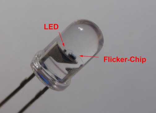
Candle flicker LEDs are a one part replacement for a real candle. They contain both a yellow LED and a control chip that modulates the light to create a candle effect. [Cpldcpu] took a deep look into reverse engineering one of these LEDs.
To analyze the circuit, which is potted into the LED itself, a shunt sense resistor was connected to the LED. By connecting this resistor to a logic analyzer, the control signal could be observed.
This control signal looked like pulse width modulation, with some randomness to the duty cycle. [Cpldcpu] determined that a linear feedback shift register was most likely used to generate a pseudeorandom bitstream, and some shaping was applied to make the LED look more like a real candle.
It turns out a blinking LED can be quite complex, and this takes a deep look into it by analyzing the signal. [Cpldcpu] took the lessons learned and wrote an implementation of the algorithm for AVR.


And I thought these just played “Happy Birthday” over and over again.
I did not know these leds existed. What I know is that flickering led tea lights are often made using a sound generating chip as modulator. see http://www.instructables.com/id/Listen-to-a-led-tea-light/
Well sound is just moving air that started moving because a coil connected to a cone responded to some electrical current.
Yes, but the point is that the “flickering” isn’t always random. Sometimes they repurpose tune-generating chips to drive an LED instead of a speaker. So what looks like flickering is actually optical “Happy Birthday”.
It’s not notable because it can make noise, it’s because it plays an actual tune.
Does Warner/Chappell Music know about this? And if yes, how can we use this to lure them into a trap and kill them with fire?
What, like a really big fire? You’d need to be stupid *and* greedy to fall for that one, so they’ll probably send the copyright lawyers in first.
Your ancient wisdom has helped me solve a problem in 2021. I thank you.
So where can such LED’s be bought for cheap.
Well maybe not “cheap” but the Dollar Store or generic cheap store will usually have these in a 2, 3, or 4 pack for $1. Considering all the batteries and switches you’d have left over also, I think it is a good deal (and convenient).
Well the dollar store will have the tea lights which may or may not be using this particular kind of LED.
This used to be a good deal when they used push-on push-off switches, they’ve moved now to a slide switch which is built into the case and not an actual switch module just a plastic nub breaking contacts. I haven’t seen them use a separate circuit (black epoxy blob) in years, they all use these stand-alone LEDs now.
U serious? Harvesting from tealights when there is a bargain of 10$ for 50 new bulk?
http://www.ebay.com/itm/50-x-LED-5mm-Yellow-Gold-Candle-Flicker-Ultra-Bright-Flickering-LEDs-Model-Prop-/161172888742
You can get red ones too.
3mm versions would be nice. They probably exist, I haven’t looked much.
http://www.ebay.co.uk/itm/50pc-Randomly-Flickering-Flicker-Flash-Flashing-5mm-LED-/390363690791
Slower delivery, but most likely cheaper delivery for people outside of America.
Problem is almost all of these “candle flicker” led’s follow a pattern and are not random. Every single one I have seen I can spot the pattern repeat, Anyone have a source that actually replicated a candle flicker instead of a pulsed pattern woth some very limited randoms added?
According to the linked page, the candle didn’t repeat during the 4 minutes he recorded it.
100% of them I have encountered are simply music chips driving the LED. you can hook up a speaker and hear the tune. Thus the repeat. and 4 minutes is not long enough to end some of the songs, Betting his is only a song chip as well and he did not wait long enough for the repeat point.
You are completely welcome to try an analysis of your own, I posted all the data in the github repository linked at the bottom.
Songs usually have some level of autocorrelation and a variation of pitch. This was all at 440Hz and without correleation. This thing is definitely not playing a song.
I agree. I use these to make “faux fireplace inserts”. I’ve never noticed a pattern. If it was based off of a song, the song would have a beat. These seem random. Even if they weren’t, who the hell can figure out a 4 minute long pattern and who cares?
I wire 10 of these up to a 1.5v power adapter and place under some burnt logs. It lights up the fireplace and gives the illusion of burning ambers.
I do know that when powered, they do not flicker in sync with each other. So when you have 10 LED’s all flickering at different intervals, you don’t notice any pattern.
@Brian, I believe the mis-sync is just due to loose specs in the manufacturing. They haven’t a need for precise timings and they and up slipping apart which is actually great. You can see this with the RGB self-cyclers especially.
The LEDs I have used to source their flicker don’t have a waveform that looks like music unless its a 3-tone song. I’ve only seen 3 levels of brightness, sourced from dollar store LEDs and bulk order from china.
It depends, perhaps some notes look the same as others! You’d really need to put a speaker in there somewhere to test it.
True, I intend to now haha. But the samples I see on the ‘net show the candle LEDs toggled by external black blob epoxy ICs, which I haven’t seen in years…
small solar cell (like one of those $1 solar garden light) and a small amp/headphone will let you hear the light pulses.
@fartface I wrote a flicker sim once that tries to simulate wind gusting dynamics, based on a pic10f chip. I had a lot of time on my hands, apperantly. Seems pretty realistic to me. http://eternityforest.com/Projects/CandleFlicker.php
well that’s neat
What was your testing methodology? Just because there was a repeat doesn’t mean that it is a music chip. It could be a badly written number generator or simply a store random sequence (which doesn’t have to be music).
@fartface You sit at home watching flickering LEDs looking for patterns? I would suggest that you get out more, but I suspect that people would avoid you if you did.
It’s not hard to spot. Especially since many restaurants are now using these they are always in your face. I notice the patterns too, especially when two candles begin fall in sync or are on a delayed sync I can see a pattern in one show up on another a moment later.
The author could try to repeat the experiment in a complete dark and an illuminated setup. Might be a (photo-sensitive) BJT or zener as a (deliberately unstable) feedback.
A very long time ago I remember reading about a flickering electronic candle project in Popular Electronics. The cool thing about that one was that they used a thermistor to control the flicker. Supposedly it actually responded if you blew on it!
Other details that I remember are using a wooden dowl for the candle body and wood glue to simulate wax drippings.
One I heard about ages ago (which actually used a torch bulb, back when they existed. Yeah, old!), used a simple loop. An LDR controlled the bulb through a simple transistor switch. While the lamp shone, the LDR kept conducting, which kept the lamp shining.
The cute bit was the effect. The LDR faced the bulb directly, mounted in a sort-of pewter candle carrier thing, the thing Victorians took to bed. The bulb starts out dark, but lighting a match and bringing it to the LDR “lights” the candle! To extinguish it, you blow it out, subtly cupping it so your hand breaks the beam going to the LDR.
If you wanted to make this using LEDs instead of a bulb, you’d either need to include a constant non-flickering LED, or a capacitor to store a bit of voltage to keep it switched on for the milliseconds while the LED flickers.
The candle-carrier in the one I saw was a cut-up plastic milk bottle, with the LDR mounted on the upper part of the handle, cut off there while the guts go in the bottom bit. Perhaps a half-litre / 1-pint bottle would be good.
I suppose if you wanted it super safe you could make the match itself out of an LED on a stick. But if you made this looking nice it’d be a cute thing to have for xmas and probably impress a few little kids. Might keep em out of your hair for a little while!
Very cool reverse engineering… Congratulations. What made me laugh most was your comment about how much time took you to do all this… I would have expected more… :-)
Thanks! I had some routine because I analyzed a very ugly protocol (SWD) a couple of days before :)
3 Words. Candle Flicker Throwies.
Awesome idea! Still got a couple of the LEDs left.
Somebody wants to decap one of these and see what the other pins on the chip do!
Arduino Bootloader anyone?
Pins??!
Reblogged this on Science and Technology Today.
I’m surprised only one person brought up the fact that these types of control chips are nothing new, there are blink circuits and at least 3 different LED fader circuits. The only really new thing is that this appears to be random or pseudo-random.
clpdcpu,
Your code on github have a bug. ‘randflag’ is never reset to zero once it as been set to 1.
should be:
if ((RAND&0x0c)!=0) randflag=1;else randflag=0;
Good find. I indeed forgot to reset it the flag. Fixed it in the repository.
well done!!!
more re-engineering please …
What if.. the candle LEDs had badBIOS on them?
Just saying…
Would be a very effective way to distribute malware, if the noise got into say a microphone input or got observed by a PC connected webcam.
:-)
“Happy Birthday” is possible, also a good one is the “Love me tender” one as a lot of these were made one year for Valentine’s and the company only sold a few hundred.
True, I can imagine a lot of bare chip dies, that were never epoxy-blobbed into greetings cards, could have been popped into LED bodies instead. They cost virtually nothing, but there’s always a profit somewhere.
Could be that they started out using surplus music chips, and saw no need to invent a replacement, so just carried on ordering more.
As for malware, well, pretty unlikely. If you can get a PC to absorb software over a microphone or camera, then you already control it. I also don’t think much of the bit rate. Over a camera it’d be something like 10 – 20 baud. Even over audio, I’m sure you remember how slow modems were, this would be at acoustic coupler rates! Not very well coupled either.
This morning I sanded most of the top off of one of these tea-light LEDs and after buffering it smooth (and with a final drop of cooking oil), had a look at the IC under the microscope. For the one I had, I can assure you that it does not have any ROM structure to contain a song (such as “Happy Birthday”). It’s at the optical limits of what I can reverse engineer with my microscope, but based on what I see there is likely an on-board oscillator, a divider chain (to lower the frequency), and some shift registers (more than likely wired to create a LFSR). There is some additional gating (which might do some sort of pulse frequency modulation of the output?), and a final transistor wired to an output pad which drives the anode of the LED. There is also an additional (unused) pad, but I’ve not yet discerned it’s function.
Impressive! Great work. If you can grab a picture from your scope I would love to see it
Sounds very interesting. Do you have any images to share?
OK, guys, here’s your Christmas present:
http://i.imgur.com/7cafiA3.jpg
Not the best chip photo, but consider the circumstances.
Here’s a few notes:
Upper left is GND pad.
Lower right is VCC pad.
Upper right is output to LED anode.
To the left of the LED output pad is the large serpentine LED driver transistor.
Between the GND pad and serpentine transistor is Power on Reset with the metal plate the capacitor and a long trace loop to form a resistor for an RC time constant.
In the lower region, to the left of the VCC pad, is a similar pad which forms a capacitor. With the serpentine resistor connected to the upper left of this pad, this, forms the on board RC oscillator. The drive transistor is center bottom with four T-flip-flop divider stages repeated to the lower left of the chip.
The middle of the chip has three horizontal bands.
The upper band (just below the GND pad and extending across to the LED pad) is a 9-stage divider chain along with miscellaneous logic at right. This divides down the RC clock. Additionally various taps from the divider chain are used in the second horizontal region.
The second horizontal region has several EXOR gates (center) which combine outputs from the divides chain, along with various outputs from region three below.
Region three has several cells wired as shift registers. Near the left is misc logic, then two shift rigisters, then an EXOR gate, then five additional shift register cells. At the far right is a buffer which then drives the previously mentioned large serpentine transistor to the LED pad.
The shift register cells are very similar to the T-flip-flop cells used in the 9-stage divider chain, but wired differently.
More details later.
That is awesome, thank you very much!
Awesome! I only saw this now. I will have to study the layout. This looks like a pretty old process geomtry. Do you have any idea about the feature size?
@Erik Johnson
car turn signals never sync either. if you are at a traffic light and you notice 2 cars getting ready to turn their blinkers are out of sync even if it is the same make model year car
for everyone else one comment suggested that there was some morse code encoded there.
it could be a way to even smuggle secrets by programming an led.
whoah this weblog iss magnificent i like studying your articles.
Keep up the good work! You know, a lot of persons are searching rohnd for this information, you can aid them greatly.
This was referenced elsewhere, so a late comment.
Pseudo random generators are an old thing. The first issue of Popular Electronics I saw, Feb 1971, had tye Psych-Tone by Don Lancaster. Random notes by a short shift register.
About 1976, National came out with the MM5437, an 8 pin IC that generated white noise. It used a long shift register with feedback from the right points. Only thre pins needed, +V, ground output.
45 years ago there were LEDs with a built in zener, so it would turn on above a voktage. There were also LEDs with built in constant current source, so no external resistor. A bit later, a red LED that blinked, it beat the LM3909 as long as the fixed rate was good enough.
So there’s nothing new about adding another chip. An LED is really small inside the epoxy lens.
And once they were making LEDs that flickered, why not use a traditional method? If they had to use an IC and LED, I can imagine using something cheap and available, but why put something that isn’t even pseudorandom into an LED?