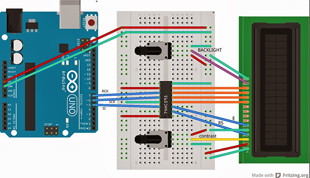
The HD44780 LCD controller is the defacto way of adding a small text display to your next project. If you need a way to display a few variables, a few lines of text, or adding a small user interface to a project, odds are you’ll be using one of these parallel LCDs. These displays require at least six control lines, and if you’re using a small microcontroller or are down to your last pins, you might want to think about controlling an LCD with a shift register.
[Matteo] used the ubiquitous ‘595 shift register configured as a serial to parallel converter to drive his LCD. Driving the LCD this way requires only three pins on the Arduino, [Matteo]’s microcontroller of choice.
For the software, [Matteo] modified the stock Arduino LiquidCrystal library and put it up on his Git. Most of the functions are left untouched, but for this build the LCD can only be used in its four bit mode. That’s not a problem for 99% of the time, but if you need custom characters on your LCD you can always connect another shift register.
If you just can’t spare three pins for a display, you could squeeze this down to just two, or add a second microcontroller for a one-wire-like interface.


I just use a drop of epoxy to dead-bug mount an ATtiny84 on the back of the LCD. That way you can use 1-wire or I2C or whatever you want. I get the tinys in 100 lot at Mouser for $0.80 ea. I get the LCDs off Ebay for about 3.00 ea. So for less than 4.00 you have an LCD that is really useful.
Ahhhh .. at last I finally know why it’s called ‘glue logic’
Or even better, go for an Attiny88-AU for 50c each. With 32 pins you don’t even need a separate arduino, The .8mm pitch pins is still manageable for hand-soldering as long as you have a fine tip.
Like it, but not enough to stop using the standard i2c board for the LCD and only using 2 analogue pins.
FTFA: squeeze this down to just two
FTFC: analogue pins…
especially since these are very cheap as well :-)
I must say though that I did a 2 wire interface with a 164 shift register that I use for attiny’s and for a nano where i wanted to use ALL the analogue ports and couldn’t sacrifice A4 and A5.
I may try the 1 wire… just for the heck of it :-)
I don’t have any blue wires. Would it still work if I used white instead?
Yes, yes it will work.
I nominate this the best comment of the day (don’t get too excited, my opinion means nothing.)
I second this.
+1 … I’m cracking up here!
White wire always work – an electron of ‘any’ colour can go down a white wire.
but you have to take into account the velocity factor due to the color of the wire.
if you are running timing-critical connections and you want all the signals to get there at the same time, you should use the same color and the same length of wire OR if you change colors, you have to account for the change in the speed of-
oh, I can’t. I just can’t. I’ll stop here.
Some electrons pick the scenic route, and white just dont cut it, they want something interresting like violet or yellow or blue. So white may not work, you have to know your electrons’ mood
Yes, but be careful not to use red wires, they are linked to the microcontroller’s self-destruct subroutines.
While the damage to your workbench will likely be negligible, there will be long term damage to the space-time continuum, possibly even fracturing subspace.
I thought that was only if you cut it … or was that the blue wire?
Just don’t use brown wires or the chip might brown-out – or at least call the fashion police.
will leave this here
http://cdn.memegenerator.net/instances/500x/45627149.jpg
Hey! You can use this to tweet the state of your toilet seat in realtime!
definitely use brown wires there :P
I saw one yesterday that was literally 2 wire (including power).
LOL, It was on HAD –
http://hackaday.com/2014/02/01/controlling-alphanumeric-lcds-with-two-wires/
No backlight though. You would need a transistor at the uC end if you want to transfer enough current to drive a backlight.
Straightly speaking when you use the SPI hardware, the HW reserved the MISO whether you are really using it or not. So in reality this is taking up 4 I/O lines instead of 3 as claimed unless you are bit banging in software.
There are LCD with SPI interface. “Nokia 5110” (graphics) which are around the same price $3 as character display from China from the usual places.
Technically speaking, you can still use the MISO pin for something else, driving something from it. The ATmega SPI interface does not set up I/O automatically, setting up the pin’s DDR is left to the user. That being said, nothing stops you from using the MISO pin as generic I/O, even with the SPI interface active. You must, however discard any data that you would obtain from SPIDR after any SPI transaction as it would be garbage in this situation [lest you are driving a second slave from the same port, in which case, four wires be needed, the fourth one as a slave select for this circuit, with its glue logic of course].
s/SPIDR/SPDR/g
Hate not being able to edit stuff…
But isn’t using SPDR’s a bit risky?
http://en.wikipedia.org/wiki/SPDR
You can use the pin only as *input*, not for *driving* signals as you claim as it is now an *input only* pin.
Page 164 of the Atmega 328 datasheet.
MISO Input (Master mode)
I did cheat using it as my Nokia 5110 /Reset. In my LCD init routine, the pin was init as an I/O and driven low As soon when SPI is turned on, I have a pull up resistor to override the pin which is now an input level to high, deasserting /Reset.
Good catch there. The USI on the tiny series works a bit different, must have mixed those up. I admit my mistake on that one, should have verified the datasheet. Cheers.
You can pair the ‘595 with some ‘165s to latch and scan out buttons while driving the LCD. You can get away with having more ‘165s than ‘595s or vice-versa since the registers are latched on /CS.
nad here we have another great alternative to the PCF8574 (i2c port expander). I guess this adds to the list of ways to save pins/routing effort/whatever. however this method doesn’t give a way to read data, which probably hardly ever is an argument.
*and
Ummm…Just use a serial display???
you are right, but the only one display i had was a parallel one :)
pwm contrast control next? anyone?
Parallax already did this, with backlighting. http://parallax.com/product/27979
Just a happy customer. :)
here is a way to control a HD44780 LCD with ONLY 1 WIRE…
http://wp.me/p4jHZx-4
it monitors the serial monitor and prints anything that comes across on the LCD.
It’s more efficient to tie both sck and rck pins to the same arduino pin and the third arduino pin to the display’s enable line. The shift register outputs will be updated on every clock cycle but that’s ok because they will only be read by the display once it’s enable pin is toggled. This way it’s not necessary to update all the bits twice serially just to toggle the enable line. I’ve done it, works like a charm.