Reverse Engineering A Sony Car Stereo LCD

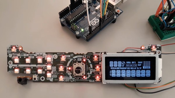
For his own reasons, [Jose Luis Monteiro] (aka [emsyscode]) decided he needed to drive the LCD on a Sony CDX-A250 car stereo’s front panel using an Arduino. There’s probably a sweet project in the works, or perhaps he just wanted to see if it could be done. Either way, more power to [Jose], because he totally pulled it off and put the results up on GitHub for all to enjoy. There’s also a project video showing how he did the reverse-engineering, which you can see below.

The driver for this diminutive LCD is a chip obviously labeled LC75826W, and that’s what the Arduino ends up talking to. Thankfully, there was a datasheet available for that part, which gave [Jose] a great starting point for figuring out how to use it. While [Jose] is working with the LC75826W driver, he’s quite explicit in his GitHub repo that this repository is not a driver library for that chip. The code only targets the specific LCD on the CDX-A250 head unit. Still, if you’ve got a different oddball LCD that uses this driver, [Jose]’s code is a great place to start, and since it’s under an MIT license, you can fork to your heart’s content.

Kudos to Sony for not obfuscating the part or using a chip-on-board black blob — you can reverse-engineer an LCD driven by one of those, but it’s a lot more work. If you’re wondering how and why those black blobs come to be, we’ve got you covered.

Continue reading “Reverse Engineering A Sony Car Stereo LCD”
One Man’s Perfect Retro-Style Monitor Takes All Inputs

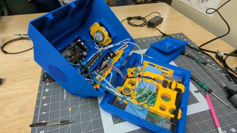
Perfection is an inherently subjective measure, in that one must choose the criteria against which to measure. A perfect circle is an absolutely rubbish octagon, for example. So when you see that [RetroBuiltGames] declares that he has built “the perfect multi-input display for retro gaming and vintage computing” — dubbed the “PixelVision AV1000 MKII”— keep in mind that he means the perfect display for his use case. That’s who he’s building it for, after all! The degree to which you find his product perfect is going to depend by-and-large how similar his use case is to yours. In that sense detailed explanations in the design/build video embedded below may be more valuable than the STEP files and PCBs in the GitHub link above– that way if your use case isn’t identical, you can perhaps learn something on the journey to build your own perfect monitor.

For [RetroBuiltGames] the aesthetic was obviously a big part of it– he’s inspired by the Amiga 1000’s monitor, and a tiny tilting Sony CRT TV.  He was obviously looking for many inputs, as given by the title, and he has an unusually high interest in pixel density for a retro enthusiast. Hence a 9.7″ 2K iPad display forms the basis of the project. The multi-input aspect is provided by a retrotink clone whose PCB lives in a bulge on the back of the unit that could easily house an SBC if you wanted an all-in-one emulation station– it already has a couple of decent speakers mounted in the sides.

Another big piece of the puzzle we don’t see enough of in such projects is Design For Manufacturing– the manufacturing method of choice being FDM 3D printing. The whole assembly was designed in chunks that can be easily printed  with the most visible surface flat on the bed – and if assembly proved difficult, than the parts were redesigned. His explanations aren’t a full DFM course by any means, but it’s good to see these things considered. If you need more detail on that front, we’ve featured plenty of such guides before.

We’re particularly taken by the conceit of creating his own packaging for the unit, and going to the effort of filming an unboxing video for a product he made himself. It’s just a bit of silly fun. We’ve seen boxes before, but generally speaking that sort of thing is saved for when a project becomes a product.

Continue reading “One Man’s Perfect Retro-Style Monitor Takes All Inputs”

How To Use Those Cute But Slightly Odd 7-Segment LCDs

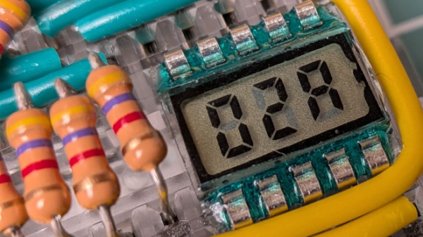
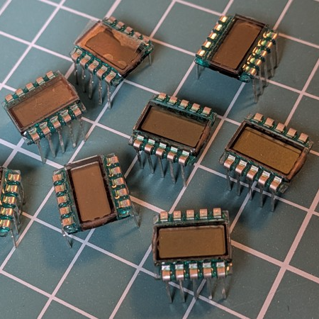
If you’re not aware, there is such a thing as adorable little three digit LCD 7-segment displays. They come in a ten-pin DIP package and are just begging to be integrated into a project. The catch is they are just a tiny bit weird. Luckily for us all, [Nagy Krisztián] spells out exactly how to use them.

The first odd thing about these ten-pin LCD displays is that they have a footprint that doesn’t quite mesh with standard 0.1 inch spacing, meaning they will not cleanly fit into a breadboard. Luckily, one can solve this with a bit of force. It’s a small part, and the pins don’t seem to mind.

These little LCDs are adorable, but a bit unusual to interface with.

The second odd thing is wrapping one’s head around the pin mapping. Figuring out the table of which pins activate which segments in the digits is easier if one keeps in mind that each segment of each digit is the product of two different pins. For example, “2A” is digit two, segment A, and is the product of pins 3 and COM4.

That’s not all. Electrically speaking, driving this LCD isn’t nearly as straightforward as an LED.

With an LED display, the COM pins are either common anode or common cathode, which tells one whether lighting up a segment means holding the COM pin at GND with voltage applied to the segment pin, or the other way around. But in the case of this LCD display, the polarity applied is swapped every cycle. Oh, and inactive COM pins need to held at half-voltage. Neat!

[Nagy] drives the whole thing with little more than an ATtiny84 microcontroller and a few resistors. A switchable half-voltage signal is cleverly created by combining a simple voltage divider and taking advantage of the fact that the ATtiny84’s pins can be in one of three different states depending on how they are configured: high, low, or high-impedance (pin configured as an input). Each COM pin on the display gets connected to both an ATtiny84 pin, and to the supply voltage via two resistors forming a voltage divider. When the ATtiny drives the pin high, the LCD pin sees about 3 V. When the pin is driven LOW, the LCD pin sees 0 V. When the ATtiny configures the pin as an input, the LCD pin receives about 1.5 V.

The bulk of the software is defining which pins and states equal which digits, and cycling the LCD at a rate of vaguely 60 Hz which delivers flicker-free results.

We appreciate the clever combination of voltage divider with pin configuration to create three switchable voltage levels. If you liked that and want to see more serious leveraging of pin configuration on a microcontroller, check out how to drive seven LEDs with only two pins.

Ebike Display Uses Reflective LCD

Although LCD displays have been used in almost every type of consumer electronics display over the last two decades, many of these screens have a few downsides that limit their usefulness in certain situations. As any owner of an early digital watch, an early laptop, or an early digital camera will testify, these displays often completely fail in direct sunlight. And, a currently new technology often using inexpensive displays in full sunlight conditions is ebikes, so [Volos Projects] decided to use a unique LCD display to solve this issue.

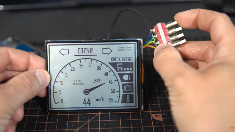
The display is called a reflective LCD (RLCD) and is actually a fairly old but overlooked piece of technology. Displays like these have a reflective layer that bounces ambient light back to the user, increasing contrast and readability in high light, especially when compared to more common transmissive displays. This build is based on a board from Waveshare, which includes the screen and its driver components, and [Volos Projects] integrated this into a test stand that mimics an ebike’s speed sensor and other hardware like turn signals. The display shows the bike’s speed and a few other indicators, and thanks to the screen, this information can be easily seen in full sun.

Although he doesn’t have it on an actual e-bike yet, he hopes it will be useful for those who want to try out something like this with their substandard e-bike displays. The code he’s used is available on a GitHub page for anyone interested. We’d imagine that a low-cost display like this would pair well with an open-source ebike like this one.

Continue reading “Ebike Display Uses Reflective LCD”

New Display For Old Multimeter

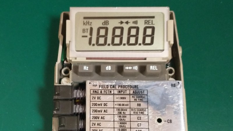
As a company, Fluke has been making electronic test equipment longer than the bipolar junction transistor has been around for. In that time they’ve developed a fairly stellar reputation for quality and consistency, but like any company they don’t support their products indefinitely. [ogdento] owns a Fluke meter that isn’t nearly as old as the BJT but still has an age well outside of the support window, and since the main problem was the broken LCD display they set about building a replacement for this retro multimeter.

Initially, [ogdento] had plans to retrofit this classic multimeter with a modern OLED, but could not find enough space for the display or a way to drive it easily. The next attempt to get something working was to build a custom one-off LCD using a drill press as an end mill, which didn’t work either. But after seeing a Charlieplexed display from [bobricius] as well as this video from EEVblog about designing custom LCDs, [ogdento] was able to not only design a custom PCB and LCD display to match the original meter, but was able to get a manufacturer in China to build them.

The new displays have a few improvements over the old; mostly they are more stylistically inspired by later Fluke models and have a few modern improvements to the LCD itself. There were are few issues during prototyping but nothing that was too hard to sort out, such as ordering the wrong size elastomeric strips initially. For anyone who needs to replace a custom LCD and can’t find replacement parts anymore, this project would be a great starting point for figuring out the process from the ground up.

A Computer That Fits Inside A Camera Lens

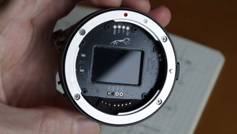
For a long while, digital single-lens reflex (DSLR) cameras were the king of the castle for professional and amateur photography. They brought large sensors, interchangeable lenses, and professional-level viewfinders to the digital world at approachable prices, and then cemented their lead when they started being used to create video as well. They’re experiencing a bit of a decline now, though, as mirrorless cameras start to dominate, and with that comes some unique opportunities. To attach a lens meant for a DSLR to a mirrorless camera, an adapter housing must be used, and [Ancient] found a way to squeeze a computer and a programmable aperture into this tiny space.

The programmable aperture is based on an LCD screen from an old cell phone. LCD screens are generally transparent until their pixels are switched, and in most uses as displays a backer is put in place so someone can make out what is on the screen. [Ancient] is removing this backer, though, allowing the LCD to be completely transparent when switched off. The screen is placed inside this lens adapter housing in the middle of a PCB where a small computer is also placed. The computer controls the LCD via a set of buttons on the outside of the housing, allowing the photographer to use this screen as a programmable aperture.

The LCD-as-aperture has a number of interesting uses that would be impossible with a standard iris aperture. Not only can it function as a standard iris aperture, but it can do things like cycle through different areas of the image in sequence, open up arbitrary parts or close off others, and a number of other unique options. It’s worth checking out the video below, as [Ancient] demonstrates many of these effects towards the end. We’ve seen some of these effects before, although those were in lenses that were mechanically controlled instead.

Continue reading “A Computer That Fits Inside A Camera Lens”

Real LED TVs Are Finally Becoming A Thing

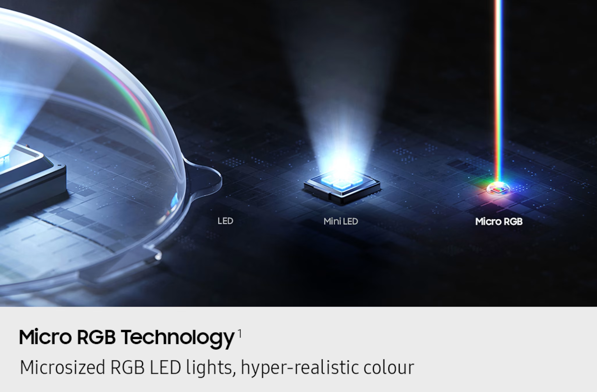
Once upon a time, the cathode ray tube was pretty much the only type of display you’d find in a consumer television. As the analog broadcast world shifted to digital, we saw the rise of plasma displays and LCDs, which offered greater resolution and much slimmer packaging. Then there was the so-called LED TV, confusingly named—for it was merely an LCD display with an LED backlight. The LEDs were merely lamps, with the liquid crystal doing all the work of displaying an image.

Today, however, we are seeing the rise of true LED displays. Sadly, decades of confusing marketing messages have polluted the terminology, making it a confusing space for the modern television enthusiast. Today, we’ll explore how these displays work and disambiguate what they’re being called in the marketplace.

Continue reading “Real LED TVs Are Finally Becoming A Thing”