[Czar] was working on a project with the Raspberry Pi using the MCP3008 analog to digital converter. The surface mount SOIC version of this chip was slightly cheaper, and there’s always a way to make that work (Portuguese, Google Translation). How [Czar] did it is fairly impressive, as it’s a bit more flexible for breadboard designs than a through-hole version, and done correctly, is an extremely sturdy hack.
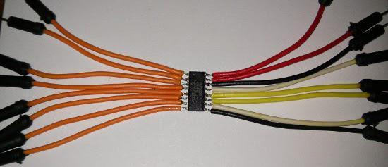
A few new leads needed to be soldered onto the SOIC package, and for this [Czar] chose jumper wires. This makes each pin easy to plug into a solderless breadboard, and since [Czar] was extremely clever, all the wires for power, ground, analog, and SPI are color coded.
Simply soldering a few jumper wires onto a chip won’t last for very long. To solve this problem, [Czar] potted the entire chip and its connections with hot glue. Probably not the best solution, and a heavy-duty epoxy would have been better, but the current build is more than enough to stand up to the relatively minor abuse it will receive on the workbench.


This is a great Hack, but I didn’t see any potting in the example photo above and question how robust those connected leads would be in a breadboard situation without potting, but then I saw it is mentioned that he did pot it, and hot glue can be sufficient in certain situations, it doesn’t need Mil Spec epoxy for this application.
I’ll second that, hotglue works great for a preventing soldered wires to break off. I have used it plenty of times with great success. I do use a hot air gun (re-flow station) to blow the glue around and really make it stick to the parts.
In addition to easy to apply, sticking your hot melt glue sealed part in the oven on 150-200 degrees upside down on a piece of cardboard; all that hot melt glue will come off in about 10 minutes rendering the part almost as good as new.
ok this is COOL
it never occurred to me you could remove hot glue by just melting it off /slaps his stupid forehead
See the link for Source Post, All Photos
This reminds me of buying a hot glue cannon, i still dont have one…
I used some stripes of an old 80-pin IDE-cable which has the same spacing as the pins of the FTDI.
http://i.imgur.com/lVHelyx.jpg
http://i.imgur.com/3fTqxfc.jpg
sand it on one side, tin it, solder the chip on it. done. easy, even for an soldering-noob like me. Then you can use the connector which came with the cable.
Awesome tip. I could be wrong. but that looks like ribon from a 40 conductor ide cable, 80 has a finer pitch and every other line is a ground line.
> buying a hot glue cannon,
The hand held things are Glue Guns.
A Glue Cannon is something that Wile-E-Coyote might use to catch Road Runner.
Heh, thanks :-)
In german, my mother tongue, its called pistol.
Unless…maybe i could order a cannon from ACME.
Have you ever tried to sandwich one of these components in a bent bit of acrylic.
You take a flat bit of acrylic, rap it in a coil of fine enamelled copper wire, heat the wire (not with a flame, use an iorn and some paper) on the top and press it in to the plastic, make two cuts accross the wire on the top to remove the middle and one cut on the other in the middle to spread out the wires. Strip the enamle from the ends of the embeded wire on both sides of the top. (don’t take off too much, fine grit diamond file perhaps or a razor blade if you have a steady hand, go with the grain) Heat the acrylic and fold it back on its self a little smaller then the ic so the tension holds it in place but doesn’t crush it.
Trial and error is the key but if you struggle to solder something that small you might have more luck this way.
I can imagine a 3d printed “adaptor” might be a bit nicer looking although threading in the copper wire might not be so strait forward.
Do you have a picture of this?
I used to solder SOIC packages onto machined DIP sockets with Teflon wire wrapping wires. It solves the strain relieve issues. After than you can plug it onto IC sockets or breadboards if you like.
Don’t spoil ADC performance with long leads. Signal Integrity issues, Ground bounce, inputs etc. They can affect the noise floor, AC performance and even shows up as noise in your DC measurements.
I remember trying to debug my school work with ADC back in school days. The whole design was on a double sided PCB (etched at school) with decoupling cap close by, but my bulk cap was 3/4″ away with a thick track. Every time I did a burst capture (controlled from a PLD), the 4th or 5th data got crazy results. Took me 2 weeks to fix the issue by placing the bulk cap on the pins. So I do take these thing very seriously.
Tried something like this, does not work well, connections break too often. But those SOIC-to-DIP PCBs are very cheap and very reliable solution, I use them all the time on the breadboard and when I have to program SOIC chip in programmer that has ZIF socket.
https://www.futurlec.com/Pictures/8PINSOIC_TO_DIP8.jpg
I could NEVER get that assembled!
I don’t mean to be a downer but this is very very bad practice. The pins on surface mount parts won’t hold up to the high heat of soldering well, plus the mechanical stress even with hot glue is just asking for headaches.
I would suggest picking up a cheap breakout board from eBay and solder it on using a hotplate or hot air pencil. Save time and avoid the trouble.
When I do this dead-bug SOICs, I first pot the pins and solder joints in epoxy, then hot glue the rest. The epoxy prevents any tension/flexing/breaking, where then the hot glue then allows slight flex without hard corners that promote metal fatigue.
When I’m bread-boarding a SOIC, I have a large pile of scrap LED leads that I solder on to each pin, epoxy the joints, then after its hardened I fan the leads out to breadboard spacing and trip them down even so they essentially become very tall DIP packages.
Using glue to fix it ? Not a hack, it’s a Chinese industrial technic ;)