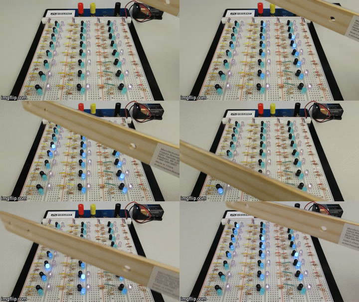
Looking for a fun and easy way to add a bit more interaction to your LED-laden projects? Why not turn them into proximity sensing LEDs?
Our hacker, [Will], is just getting into designing his own PCBs. He was looking for a simple project to try out that wouldn’t be too hard to design and manufacture a PCB for, so he came up with this clever little interactive LED array.
It’s actually a very simple circuit which also makes it super easy to build on a prototyping breadboard. Each proximity sensing LED is made up of five components. Three resistors, an LED, an IR LED, and a photo transistor. The IR LED is chosen specifically for the type of photo transistor being used — in this case, it emits a wavelength of 880nm, which is the type of light the photo transistor recognizes.
These components are wired in a manner that the IR LEDs are always on. The normal LED is wired in series with the photo transistor, and thus the LED only turns on when the photo transistor sees reflected 880nm light bounced back at it by whatever object you wave over top.
What would be really cool is if you added some 555 timers to the mix and had a delay before the LEDs fade away — then you could have a huge array that leaves motion trails long after you’ve triggered the sensors!
[via Dangerous Prototypes]


555 timers are cool, but why not just put a capacitor in parallel with the output LED to give it some fade time?
+1, there is no need for 555, capacitor and transistor would be enough.
It’s not exactly proximity sensing LEDs… It’s just a basic IR range finder.
If you want proximity sensing, then there’s this from ancient history: http://amasci.com/emotor/chargdet.html
No need for a 555. A diode a capacitor and a resistor per led are enough
Why the need for the photodiode? Could you not make use of the LE alread there, as in this article http://www.thebox.myzen.co.uk/Workshop/LED_Sensing.html
Because this requires a microcontroller?
Seeing as this started out as a basic pcb making exercise, anyone have the diagram for the diode + capacitor combo? I’ve been looking into making circuits myself and it would be fun to make a few of these. (With and without the delay).
A very simple way with just a capacitor: http://www.labradoc.com/i/follower/p/electronics-led-fade. Downside is capacitor needs to be fairly large to power the LED, and will take a while to charge (so a short fade out time).
The resistor & capacitor version as mentioned is like this: pcbheaven.com/circuitpages/LED_Off_Delay/http://www.labradoc.com/i/follower/p/electronics-led-fade (ignore the variable resistor R3).
In this version the capacitor supplies current to the transistor base when the switch is opened, keeping the transistor turned on. As the capacitor voltage drops, the current supplied to the transistor base via R2 drops as well, gradually turning it off.
Hmm. That’s http://pcbheaven.com/circuitpages/LED_Off_Delay/ for the 2nd link.
Nice. But one can cut down on IR LEDs count by using one power IR LED to illuminate the whole thing and putting the IR phototransistor in parallel with the visible wavelength LEDs.
You’d need to position the IR diode rather carefully for that to work.
Yes, the positioning in this case might be tricky. It starts to depend on a particular setup. But just as an idea…
That’s all because personally I’m too lazy to solder/assemble that much of components. :) So I’m naturally searching ways to make things simpler in terms of component count. :)
Seeing the current setup, the emitter and phototransistor-LED pair are far apart enough to have a few phototransistor-LED pair grouped around 1 emitter.
Something like a honeycomb pattern would work, one emitter surrounded by six receivers. Each receiver would be between two emitters (ignoring the edges).
Bit hard to lay out on a breadboard though.
How would the 555 be connected for fading it? When i read the last line i naturally thought of a capacitor, but not sure how would the 555 be powered to do a cycle while the transistor would be already off?
Is the 47K resistor actually necessary? Seems like it would work without it for such an undemanding app.
I guess no. But being present there it’ll do no harm. :)
You’re in luck! The “GET OUT OF MY LAWN” meme still doesn’t exist.