The new hotness for Internet of Things hardware is the ESP8266. Alone it can connect to a WiFi network, but it doesn’t really have a lot of output options. Paired with an ATMega, and you really have something. That’s the philosophy behind the WIOT board, and when [Chris] was assembling these boards, he needed a way to flash firmware. The board has an unpopulated ISP header from the assembler, so pogo pins are the answer. How do you make a pogo pin jig? With a 3D printer, of course.
The ISP header wasn’t populated to give the board a slim profile, but this means a jig of sorts would be needed to program the WIOT. The first attempt was buying a few pogo pin adapters from Tindie, but this was terribly uncomfortable to hold while the board was being programmed.
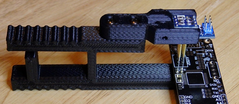
To fix this problem, a small clip device was rigged up, printed out, and used for programming. Interestingly, this clip has a very deep throat, and a few holes used for bolting on a separate programmer. This shows a lot of forward thinking: the programmer can be reused for different boards with completely different layouts and programmers. If the next revision of the WIOT needs a JTAG header to program the micro, the problem of programming it is already covered.


I kind of felt the same pain with regards to pogo pin ISP adapters. I used to use the SparkFun one, but decided to make my own. The “innovation” I came up with is a right-angle DIP plug on the bottom board so the plug goes on horizontally and the ribbon cable goes down. I think it fits in the hand better. For most of my smaller projects I now use a special ISP header designed exclusively to receive pogo programmers. Only two of the pads are actually through-hole vias and the other four are just SMD pads.
Anyway, I sell my pogo adapter on Tindie. Not sure if mine is one of the ones the submitter tried (mine isn’t what’s pictured).
https://www.tindie.com/products/nsayer/avr-isp-pogo-adapter-kit/
Another alternative I like is the http://www.tag-connect.com/ for SWD or JTAG programming. They cost a bit more, but are a smaller and sturdier footprint for a pogo based cable. I use them on my hackaday.io projects.
Stupid question, probably, but I’ll ask anyway: What’s the benefit of Pogo pins compared to just using a normal 6-pin header? In other words, assume you’ve put 6 SMT pads or small vias on the PCB in a 2×3 array with 0.1″ spacing. Now you want to connect to these 6 pads/vias to program the AVR on the board. Is there some reason Pogo pins are superior for this task compared to just a 2×3 0.1″ header you probably already have lying around the parts bin?
If you used non-spring-loaded pins, it would only be possible to get reliable contact with up to three pins. Four or more pins and you get the tippy-table problem.
Generally you would use pogo pin jigs when you are doing higher volume production. You remove the cost of the header and the assembly cost, which really adds up. It’s also better for the longevity of the programmer, since you’re not plugging and unplugging a lot. Then there’s the ergonomics and frustration with having to put the programmer connector on and off.
Pogo pins are awesome for repeated tasks.
Nice design! Personally, i like the newer models of the ESP8266 which have a lot more IO options, my ESP-12 has 9 IO lines + Serial!
If you got the tools, use them. ^^
I, for this particular purpose, would have skipped altogether the 3D printed part and assembled something else, just because would have taken much less time.
Yeah kinda agree i setup my pogo pins and gobed hot gule not the most reliable thing but i was only doing 50 or so boards.
http://postimg.org/image/phy9xsrcl/
Wow, that is not pretty (no offense intended) – but great job. I like that you have a crystal in there, too.
Yeah it was a hack for sure:)
Talk about kludging… I love it. Any issues with temperature affecting the components?
After programming more than a few boards trying to apply sufficient pressure to engage the pogo pins with just my hand, I’m never doing that again. Ouch.
Sorry if this is inappropriate, but the words cockrum and deep throat have a NSFW feel to them…also statistically geeks and nerds are better at pleasure and have more fetishes that their normal counterparts…
I confirm I grinned reading “deep throat” :D nice setup btw
Cheers
Totally. I had to rub my sender up against my partner’s sorgan as soon as I read it!
Or use the ATMega to do the usb to serial and pull down the appropriate programming pin on the 8266 to flash the firmware (I assume you dont require 115200 baud to program).
Note also both ATMega and ESP8266 can run on a lot less than 3.3V if your having issues.(I’m guessing your keeping 3.3V for I/O purposes though!)
Nice project though :-)
Shameless plug for my mostly 3d printed quadcopter pogo pin jig project: http://hackaday.io/project/4751-bradwii-on-the-hubsan-q4
There’s another reason for the ‘deep throat’ – the centre bar is meant to flex slightly when the handle end is squeezed, and without the throat that flex wouldn’t be sufficient to open up the programmer end.
So… my soda happened to have spilled all over my keyboard due to laughing. Please tell me that was intended. If you was serious, bravo for the use of double entendre.
The pogo pin adapter you have is sold here https://www.tindie.com/products/FemtoCow/pogo-pin-iscp-spi-programmer-adapter/ it’s quite easy to hold unlike others because it’s so slim, but programming multiple boards or even a single one if the program takes too long to upload can be pain, longer you hold it, more tired you get, that’s just how it is and for that it’s nice to have a rig