Over the last decade or so, USB has somehow changed. It’s not just for connecting printers, keyboards, mice, and webcams any more. It’s not even just for stuff you would have plugged into a serial port. It’s a power outlet. If you want to charge your phone, plug it into a power outlet that can deliver up to 2.5 Watts. Unintended consequences, I guess. If you ever find yourself in 1995 again, go over to Intel and tell them to bump up the current limit.
Being a power outlet, having a device to measure current, voltage, power, and all the other intricacies of the what’s going on inside a USB cable would be neat. The USB Tester from Fried Circuits is that device.
 The Fried Circuits USB tester isn’t so much a single device, but a small set of tools that allow you to probe everything going on inside a USB cable. In its simplest form, it’s just a board with a USB A connector at one end, a USB micro connector at the other, and breakouts for measuring current, voltage, the differential data signals, and that weird ID pin that’s useful if you’re working with USB chargers or OTG devices.
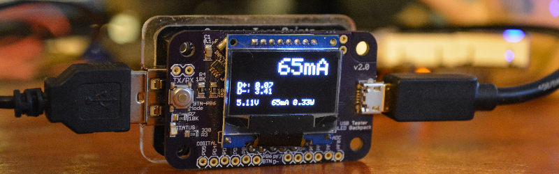
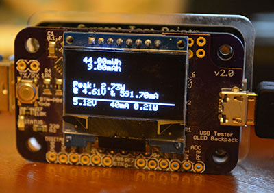
This breakout board also has two rows of five pins broken out. That’s for the USB Tester Backpack, which is really the heart of this device. This backpack features a microcontroller and a 128×64 resolution OLED display for current, voltage, and power monitoring, reading the voltage on the data lines, and graphing everything on the display. Everything you would ever want to know about a USB port – except for the actual bits being shoved through, of course – is right there on the display. Press the button on the side a few times, and whatever info you need will be presented in tall, very readable numbers.
The Entire Reason For Buying One
If you’re only going to use this to look at voltages, amps, and current flowing through a USB cable, you’re throwing your money away with this USB Tester. If simple, at-a-glance monitoring is what you need, you can hop on Amazon and get a USB current/voltage meter for $15. Even Adafruit has one for $7.50. If you only need to read the volts and amps for a USB device, your money is better spent elsewhere.
The Fried Circuits USB tester does something none of these other USB meters can do. It can log all the data to a computer over USB.
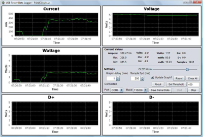
In my initial review of the USB Tester for the Hackaday Store, the only ‘official’ option for recording data from the Tester to a computer was a Java app. The developer of the USB Tester, [Will], chose Java because of the ‘write once, run anywhere’ Sun and Oracle have been shoving down our throats for the last 20 years. In theory, Java was an excellent choice for a datalogging solution for the USB Tester.
In practice, however, it just didn’t work. By [Will]’s own admission, it was the first thing he’s ever done in Java, and I think he set some of the options in NetBeans wrong. I could not get the data logging app to run on my Windows 8 box, or my OS X box, or my Linux boxxen. The only way I could run this app was by digging out an old XP box. Apparently, [Will]’s copy of NetBeans was configured for Java 5 or something.
[Will] knew about this problem, and last month he officially teamed up with [Edouard Lafargue] of wizkers.io. This is a platform for scientific instruments that runs in a Chrome App. The choice of running instrumentation in a Chrome app may seem odd, but this is apparently the new hotness; you can program an Arduino in a Chrome app, and there’s a lot of interesting stuff happening in this space.
You can try out the Chrome app right here, and with the USB Tester everything works as intended:
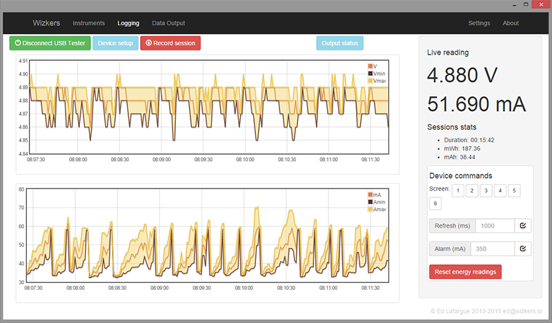
The Wizkers.io app can do everything you would expect from a datalogging app. It will tell you the volts, amps, watts, mWh, and mAh of the device currently under test. There are pretty graphs, and everything can be downloaded to a computer for further analysis.
It might seem like cheating to review this device with a 3rd party app, but by [Will]’s own admission, there were problems with the Java-based logger, and the Chrome app works perfectly. There’s also the delicious irony that a Chrome app is more portable than one written in Java. I appreciate that.
Of course the USB Tester also outputs this data over a serial connection (in JSON format, too!). If you just want to connect this to a computer, solder up some wires to the TX and RX lines.
Conclusion
If you want a device that just tells you how many mA a USB device is sucking up, you don’t need this. You can buy something for less than $10 that will tell you that. If you’re developing some USB hardware, you’ll eventually want to characterize how much power your device is drawing and when it’s drawing that much power. This will require a data logging tool, and apart from cutting up a few USB cables and wiring it into an expensive power supply, you can’t do better than the Fried Circuits USB tester.


needs different power input option instead of the micro 5pin usb
Ah, we have an iPhone user in the comments…
There is the VA Tester with screw terminals. Or do you mean USB output with say screw terminal input?
Hi, Thanks for the review!. One thing I would like to add is there is a VA Tester base so you are not limited to just USB devices. You can do up to 26V and 3.2A. The voltage limitations is just with the backpack due to the limits of the INA219B.
http://store.hackaday.com/collections/products-tools/products/va-tester-kit
Also all the source for the design and code is on http://github.com/friedcircuits and documentation is on http://friedcircuits.us/docs (Site is iin the middle of make over. Just need to finish cleaning up the guides.)
The current shipping version has a newer firmware with cleaned up screens and bar graphs. Wizers.io can update the firmware or you can download the code or the hex from github.
There is Windows exe (github) that helps with the Java environment if you want to try the Java version. I will be compiling a new version with a newer Java and a fix for internationalization soon. This will be the last version and wizkers.io will be the main tool going forward. But I will try and keep it running as newer Java versions are released.
My last note is there will be a Android app(contact me for beta access) that works over OTG or BTLE when the hardware is ready. I haven’t made an official announcement but there should be one soon.
I want to thank Hackaday for their support. Even before the backpack existed the site has helped me get the USB Tester out there.
Thanks Hackaday for the review! Will and I have worked closely on adding support for the USB tester to Wizkers.io, and the integration is really working well.
A couple of things readers might be interested in:
– The chrome app works 100% offline, no need for an Internet connection – lots of people tend to assume a Chrome app won’t work without Internet.
– Wizkers can update the firmware of Will’s USB tester, super simple process, just click on “get latest firmware”.
– There is a pretty nifty “output plugin” mechanism that lets you forward the data coming from any device supported by Wizkers to other systems.
– Wizkers is not only a Chrome app! You can run it from a BeagleBone/RPi/etc – turns your USB tester into a network-connected remote tester, how fancy is that.
– Visit http://wizkers.io/ , you will see all the instruments that are currently supported, new ones are added all the time, and if you want to contribute, this leads me to the next point:
– Wizkers is 100% open source, under the AGPL license.
Don’t stop on USB, programmable dummy load with data log would be very nice feature. We all use batteries and device that can discharge battery on desired current to desired cut-off voltage with EEPROM (or flash) log that can later be transfered to PC would be every maker’s must-have device.
“If you ever find yourself in 1995 again, go over to Intel and tell them to bump up the current limit”. You want 2A over USB? Doing so would mean the laptops with 3+ USB ports may need a bigger power supply, bigger battery, more fire risk…
True, if USB didn’t have a power negotiation phase at enumeration. It’s supposed to let the host manage its power envelope. My concern would be all of the cheapo cables with 28GA wire trying to pass all of that current. That’s why Type C is sort of cool as it bumps up the voltage to pass more power without needing huge wires.
Just wait until someone builds a Type C device killer though. As part of the new power delivery scheme, they introduced electronically marked cable assemblies with some intelligence in them. Not all that hard to imagine how one could spoof some of the configuration channel traffic and apply 20V to something that can’t handle it. I fully expect a presentation at the next Defcon…
Because you believe that if any single USB port is capable of sourcing more power, then *all* of them must be capable of doing so, *simultaneously*?
If you have 4x USB ports on your laptop, each capable of simultaneously sourcing 500mA, then it’s safe to say there’s at least a 2A power supply backing them. Plug in any three common USB devices and you’ve used maybe 200mA. Then plug in a phone that needs charging. Now if that phone simply request “whatever power is left over”, it would be getting 1.8A, certainly better than the 500mA present max. No bigger power supply, bigger battery, or increased fire risk necessary.
In fact, since many USB ports default to 500mA until a peripheral tells it otherwise, you could probably make a custom USB cable that terminates in *four* USB plugs on the laptop side, with power lines interconnected, possibly by some current balancing resistors or routing diodes. Leave the data lines disconnected. Plug that sucker into all four of your laptop USB ports, and hey, you’re charging your phone at 2A. It would just be inconvenient, since you’d have to free all those ports before plugging in your “hydra” cable; raising the current limit of any single port would still be nicer. (Though I’m not sure it’s actually this simple, I take the existence of some external HDD cases that harvest power through 2x USB connections simultaneously to suggest it’s possible.)
Chris, I remember USB standard is 100mA per device unless requested and approved more than that. However most mainboards are equipped with some poly fuse protecting at over 500mA per port.
You’re right, only 100mA is *guaranteed* unless higher is successfully negotiated. However, I don’t believe there’s anything in the spec saying that a host cannot, at its own discretion, provide more prior to negotiation. I’ve seen multiple reports of reasonably new computers providing 500mA right from the start. Here’s one example, dated 2011:
http://www.experts-exchange.com/Hardware/Desktops/PCs/Q_26961942.html
For another claim of this behavior, the above contains another link to a Sparkfun product, a USB-powered 5V/3.3V 500mA power supply – with no components that can perform negotiation. One of the comments:
“I’ve read that the 100mA limit is working only if a device is connected to the USB port. If you leave D-/+ pins disconnected, the port thinks there is no device, so it doesn’t bother limiting the current to 100mA (but surprisingly power is available anyways.)”
I’ve also seen someone drive a white LED at 350mA straight from USB power lines, with series current limiting resistor, for lighting a nano aquarium. And so on. I wouldn’t suggest relying on this behavior for commercial product, even if Sparkfun and various Chinese USB gizmos do. But if I’m hacking together a fast phone charger or whatnot for personal use, and it works, that’s all that matters.
In a previous life I worked on the desktop computer design team at one of the formerly major computer manufacturers, back in the Pentium 4 days. Our motherboards were slightly redesigned versions of the motherboards designed by Intel’s retail motherboard division.
Back then there was NO software controlled current limiting of any of the USB ports on any of our motherboards or Intel’s retail motherboards. The way it worked was that USB ports were paired together and current limited with a 1 amp polyfuse resettable fuse. The two front panel USBs were paralleled and connected to a 1A polyfuse. The 6-stack USB on the back had 3 polyfuses.
The other side of these polyfuses were connected directly to the motherboards 5V rail.
There was NO software control over any of the power delivery over any port.
So If you were using only 1 port of each pair you could pull 1A with no USB communication, with NO request for additional current.
Worse, these polyfuses have a huge variation over temperature and manufacturing runs, so to guarantee you could get 1A out of a pair of ports the fuse had to be over rated, more like 1.5A if I remember right. So if you computer ran cool inside you could probably pull well over an amp for a long time.
A bad side effect of this is that if you short out the power on a USB port you will reset the computer because it will drag the 5V rail down before the polyfuse trips. I tested this on several motherboard designs to make sure the polyfuse tripped before there was permanent damage to the board.
Now I have no idea if the situation has changed with USB 3.0 or USB-C connectors.
Yeah, but on the other side, my (desktop) computer’s PSU can deliver about 30 amps on 5V rail, computer uses few amps and the rest is not used at all. Put one SATA power connector close to USB ports and you can deliver tens of amps without any trouble. You would be able to power 3.5″ HDDs only with USB connector, you can power printer, oscilloscope, whatever. If you make short circuit USB port turns power off and you can’t use it until it’s power cycled.
How much trouble is it to add a low res current monitor on the motherboard itself? We can already read CPU temperatures, fan speeds etc. The manufacturers might just add this functionality, given that USB is increasingly being abused as a power hub.
FYI: You can find some similar to these testers on dx.com and they are pretty cheap.
Hm, only USB-Meter?
I build something similar… but its not only for USB stuff and the measure is isolated.
My decision was also a google chrome app. Where else did you get a HID cross platform compatibilit so easy?
My PowerMeter project:
https://sebastianfoerster86.wordpress.com/2015/04/03/powermeter-mess-und-anschlussbeispiele/
PS: like the OLED Display… I was adding a RS485 interface to my version for this kind of future use.
You can swap the bottom with the VA Tester which allows for non USB devices.
What do you mean HID cross platform? I am using the Atmega32U4 with native USB.
Ah, nice…
Sure you use native USB… with serial protocol (CDC) ? This protocol and more easier HID USB class are both supported by chrome apps out of the box…
I like the chrome apps… easy to install, USB cross platform compatible and graphics with html5, css and js
Maybe we could work together on an own chrome app?
Thats my current state of a working chrome app:
https://sebastianfoerster86.wordpress.com/2015/06/20/powermeter-google-chrome-app/
No line graphs at the time but the gauge meter and the csv export are working =)
Its all on my github account…
And I was hoping for a cheap alternative to the TotalPhase Beagle USB and Ellisys USB Explorer protocol analyzers…
After all, these are just USB PHYs paired with an FPGA.
Everyone who made devices like this did not bother to think that 2 cables and 2 sets of connectors would drop more voltage and increase the resistance enough to affect the current availability of the phone.
Exactly. I made an extension cable of 3 feet long with 2 pairs of 24AWG in parallel (~= AWG21) for the power connection. The regular USB cables from the Dollar store aren’t built like that at all. Even then when I added the cable the voltage drop drops the iOS charging current from 2A to 1.5A. The setup already affect the results you are trying to measure, so splicing USB cable might be better.
The cheap USB tester from china uses a 2-3 inches cable soldered directly (probably more for cost reasons). One I opened uses a 0.050 ohms sampling resistor.
Hi, I have taken that into account. The bottom base has its own connector which works better than using the data logging port as the power source. Also all traces are pretty thick. I also sell 1.5ft USB cables to reduce the distance. The reason I used a micro USB is so you can have it on your desk where you USB ports might be hidden away. I have done testing and it doesn’t affect it too much.
Now if you are using a new quick charge 2.0 you have to be careful since the voltage is above 5V. On the backside of the OLED backpack there is a shared power solder jumper you can cut. Then use a separate 5V supply for the OLED and you can measure the higher voltage.
On first sight, I thought this was a sexier version of the USB Wrapper (posted 21 March, 2014), with the OLED display for the Danger, Will Robinson warning when the logic at the other end was trying to jack you up.
You lost me with the “Chrome-app”. I hate Chrome so much I won’t let it on any of my machines. Let me know when you recompile it under a more recent Java (even better) with C.
I have recompiled the Java app with the latest Java version so it should work. Its on http://github.com/friedcircuits. I originally wrote it on Win7 so not sure what the issues were. I also know of someone who wrote a Windows app if you are interested.