If you’ve ever turned a rotary encoder or pushed a cursor button and had it skip a step or two, you’ve suffered directly from button bounce. My old car stereo and my current in-car GPS navigator both have this problem, and it drives me nuts. One button press should be one button press. How hard is that to get right?
In the last session of Embed with Elliot, we looked into exactly how hard it is to get right and concluded that it wasn’t actually all that bad, as long as you’re willing to throw some circuitry at the problem, or accept some sluggishness in software. But engineers cut corners on hardware designs, and parts age and get dirty. Making something as “simple” as a button work with ultra-fast microcontrollers ends up being non-trivial.
And unsurprisingly, for a problem this ubiquitous, there are a myriad of solutions. Some are good, some are bad, and others just have trade-offs. In this installment, we’re going to look at something special: a debouncer that uses minimal resources and is reasonably straightforward in its operation, yet which can debounce along with the best of ’em.
In short, I’ll introduce you to what I think is The Ultimate Debouncer(tm)! And if you don’t agree by the end of this article, I’ll give you your money back.
Debouncing
First, a quick recap. When you press a physical button, two metal surfaces come into contact with each other. Between the time when they’re unambiguously separate and when they’re mashed together so well that they’re making contact in multiple locations, there’s a short period of time when the button is making and breaking contact due to the slight imperfections in the two surfaces.
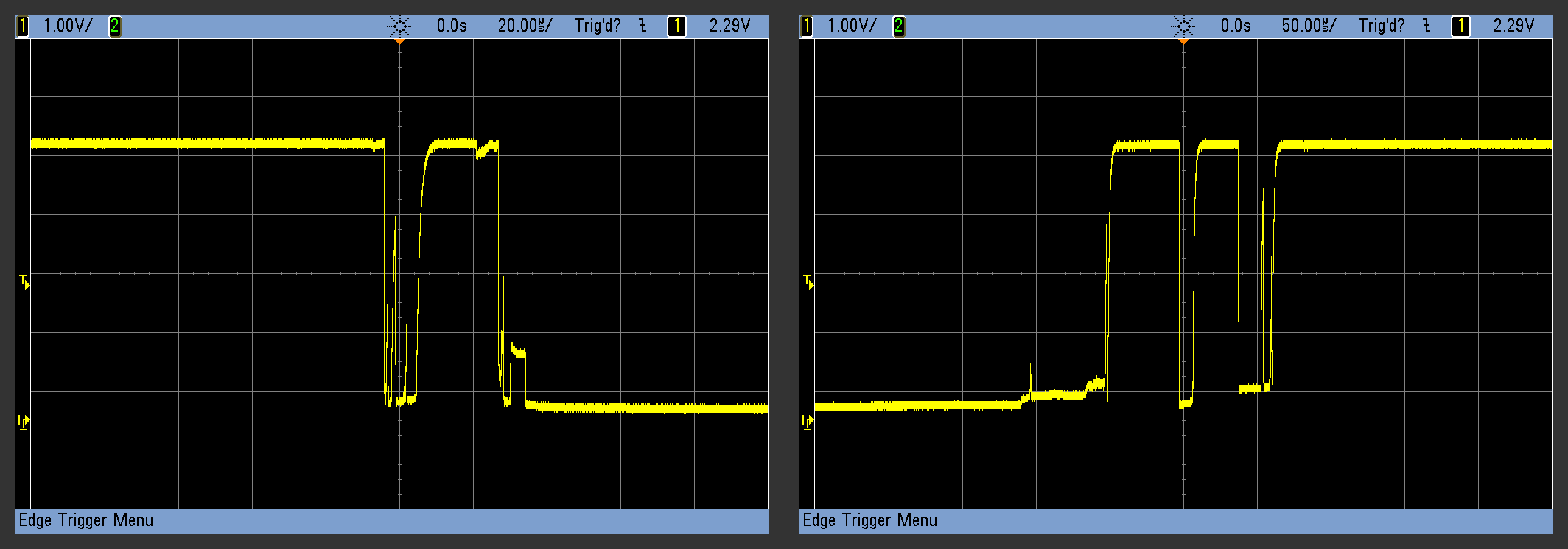
The result is that, for a handful of milliseconds, the voltage level on the switch terminal is erratic and flickers between on and off. If your code detects a button press, for instance, by looking for a high to low voltage transition, it might see multiple such transitions for what you think is a single press.
You can clean this up in hardware with the classic RC filter plus inverter-with-hysteresis combo, or you can try to fix it in software with a debouncing routine. Last time, I broke down the software routines into three classes based on how they work: by delaying until the bounce is done, by smoothing (integrating) the bounce away, or by attempting to match the button pattern as a whole.
A Difference-based Debouncer
Before we get into the Ultimate, let’s look at the “Penultimate Debouncer”. I learned this trick from Jack Ganssle’s amazing two-part treatise on button bounce (part two) many years ago, and it’s almost perfect. We’ll work through his version first, because it’s good enough by itself most of the time, and because it’s a good starting place.
One of the debounce routines that [Jack] suggested is particularly simple. The microcontroller periodically polls the button, and stores not just its current state, but a much longer history of the button’s logic voltage levels, in memory. The trick to detect a button press, then, is just to recognize which specific histories correspond to which button events (press or release) or which long-run states (up or down). That’s why I think of this as being a “pattern matching” debounce routine at heart, but I don’t think that [Jack] knew it at the time.
The nice thing about this algorithm is that is splits neatly into two parts: an updater that stores the button’s history, and various analysis functions that look for their corresponding patterns. Our API will look something like this:
void update_button(uint8_t *button_history);

uint8_t is_button_up(uint8_t *button_history);
uint8_t is_button_down(uint8_t *button_history);
uint8_t is_button_press(uint8_t *button_history);
uint8_t is_button_release(uint8_t *button_history);

uint8_t read_button(void);
Your code just has to call the update function periodically — anything from every millisecond to every ten milliseconds is probably OK. It’s best if it’s actually regular, and the update function is short enough that you could call it from a system tick routine.
Then, when you want to know what the button’s up to, you just call the respective functions and they return a one or zero. The way I’m implementing it, the button’s history is defined in the main routine and then passed to the various button routines by pointer, but this is a matter of choice. If you’re implementing many buttons, or with a strange architecture, you’re going to change this stuff anyway.
If you’re not using an 8-bit microcontroller, for instance, these routines work even better with a 16-bit or 32-bit wide history.
I’m also assuming that you’ve got a read_button() function that returns a one if the button pin currently has the voltage on it that corresponds to a button press, and a zero otherwise. In AVR C, this is as simple as ( (PORTD & (1<<PD2)) == 0 ) for instance. On an Arduino, this would be digitalRead(pin) == 0;.
Storing the History
First let’s consider the updater. A button has only two electrical states: high and low voltage. It may be bouncing between them over time, but we can think of its state as being one bit. In true embedded programming form, we’re going to store each of these bits one at a time in a byte (or word). Using bit-shift operations, this turns out to be exceptionally easy, and it’ll run ridiculously fast on most microcontrollers.
void update_button(uint8_t *button_history){
    *button_history = *button_history << 1;
    *button_history |= read_button();
}
We’re only doing the minimum of what we need to here. The updater function takes (a pointer to) the button history, and the first line is a bit-shift, which rolls in a zero from the right-hand side. If history = 0b00110101 before the shift, history = 0b01101010 after. The result of our read_button() function is written into the newly-opened first bit position. That’s all there is to it.
Compared to the tangled web of if...then statements in the delay debounce’s update function, this one is blindingly fast. It’s short enough that you can incorporate it directly into a system-tick interrupt routine if you want to. The rest of the job is interpreting the bit sequences, and that’s where the secret sauce is located.
Finding the Button Press
So we’ve got this constantly updated stream of ones and zeros flying past. [Jack]’s idea was to look for the bit pattern that corresponds to a button press. Without giving too much away, this is going to reduce the problem of detecting our various button states to simply comparing button_history to a specific value.
Imagine the bitstream that corresponds to a non-bouncing button press: ...0000000011111111111... and so on. You could test for a bitstream like 00001111 and you’d detect the press. But think about how a bouncing button press looks: ...0000100101111111111.... The crucial eight bits are 01111111 — the last bit of the bounce followed by the solid stream of pressed values. Here’s the 8-bit version of [Jack]’s button-press detector:
uint8_t is_button_pressed(uint8_t button_history){
    return (button_history == 0b01111111);
}
Wow, that’s simple — the entire routine just checks to see if button_history is 0b01111111. Detecting a release is then a test for 0b10000000 and the up and down states are 0b00000000 and 0b11111111 respectively. The memory overhead is small, all of the functions are essentially one-liners, and the update and test functions are separable. There’s no need to keep track of what state the button is in, or so it seems, because 0b01111111 already contains the notion of a state change between unpressed and pressed. And it works surprisingly well. At least for the specific purpose of debouncing.
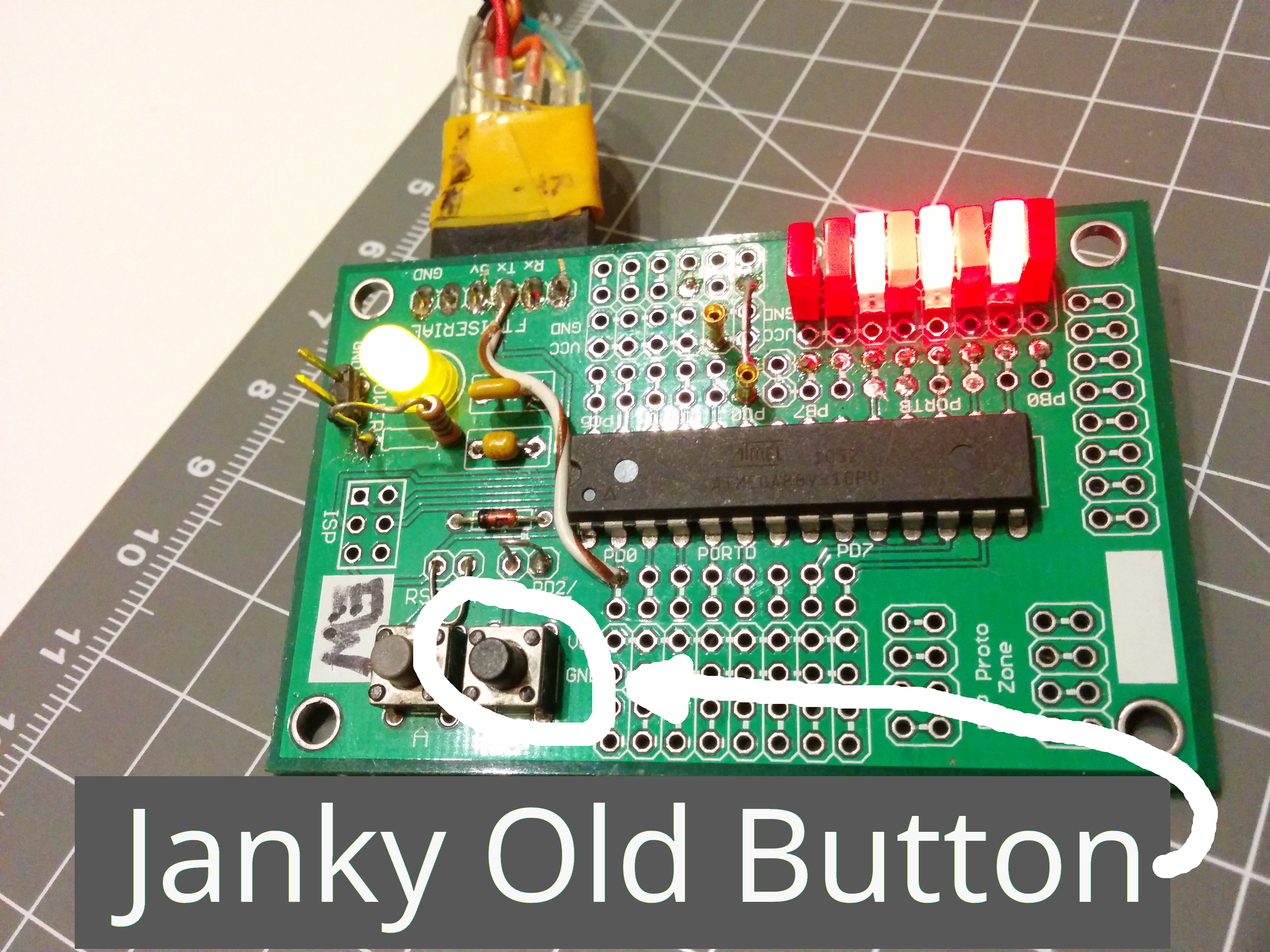
But I’ve got some janky buttons in my junk drawer that revealed a subtle flaw in the logic. For instance, I have one button that will occasionally glitch while you’re holding it down. It emits bit patterns that look like ...11110111111... even though I’m holding the button solidly down. Worse, it’ll do that a few tens to hundreds of milliseconds after the button press took place.
My intermittent button triggers a spurious button press event in [Jack]’s debouncer. A single zero in the bitstream arguably shouldn’t retrigger a button press event, but with this algorithm it invariably does. Similarly, a single high-voltage spike would insert a one into the history, resulting in a false double-release, but I think that’s less likely.
And note that the delay debouncer wouldn’t fall for this. It keeps track of the button’s state, and only tests for a button press event when it’s in the “up” state. Our glitchy 1111111011111 wouldn’t fool it because the button would already be in the “down” state, and you can’t press a button that’s already down. Indeed, the delay debouncer, aside from the code bloat, seems to be very robust because of its internal state machine. It’s not a bad method at all.
The Ultimate Debouncer(tm)
But we can do better. The trick is to take the essential logic from [Jack]’s debouncer but improve on the detection function. That actually shouldn’t be hard, because all [Jack]’s test is doing is differencing the data — testing for a change that persists. But what would happen if we looked at the entirety of the bounce?

People are great pattern recognizers. What do you see in the bounce graphs? You see three regimes — one where the voltage is constant, one where it’s wiggly, and one where it’s constant again, but opposite of the initial state. Let’s build on that; we’ll test for a period of highs, then throw away some of the junk in the middle, and then test for a period of lows. Depending on where we sampled it, the example button press might look like 111110100000 or 111110110000. Both of these match the 8-bit value 11xxx000, where x represents a don’t-care bit. Similarly, the release here is something like 0000011011111 or 000001010111111 or similar. These will match 00xxx111, with the advantage that our intermittent glitch sequence 1111110111111 will never match it. Now we’re getting somewhere. (OK, a two-period intermittent will match — either update more slowly or store more bits of history.)
We’re not done yet, though. Once we’ve detected a press or release event, we need to clear out the don’t-care section. Otherwise, we’ll detect multiple presses. For instance a no-bounce transition would trigger four times as it moves through the history: 00000111, 00001111, 00011111, and 00111111 all correspond to valid press events. So we’ll need to reset the history once a valid press is detected. And that’s as easy as resetting it to 11111111 — the history that corresponds to the “down” state, which makes logical sense after the button has been pressed.
In addition to preventing (false) re-triggering, this over-writing of the history buys us a bit of hysteresis. Beforehand, there could be bouncy zeros hiding in any of the don’t-care bits, waiting to trip us up in short order. But now that everything is written to all ones, it’s going to take a little bit more time for a zero to get over into the left-hand side. We’ve made it easier for a button release event to be detected after a press, and that’s just what we want.
Implementation
The rest of the debouncer is details. I’ll implement the don’t care region by setting the middle bits to zero in the comparison and then testing for zeros there. Resetting the button history will require that our testing functions are able to write the button history as well as read it, suggesting that the history is passed into those functions by pointers again.
Here, for instance is a function to test for a button press:
#define MASK   0b11000111

uint8_t is_button_pressed(uint8_t *button_history){
    uint8_t pressed = 0;
    if ((*button_history & MASK) == 0b00000111){
        pressed = 1;
        *button_history = 0b11111111;
    }
    return pressed;
}
Compared to [Jack]’s detection code, it looks a lot more complicated, but it’s actually only a few cycles slower. The function takes in (a pointer to) the button history, and then logically-ANDs it with our mask. That has the effect of saving each bit where the mask is a one, and zeroing each bit where the mask is a zero, but it does it very efficiently on a microcontroller.
This altered history value is compared with a number that has zeros at the front, zeros in the don’t-care region, and ones at the back. This corresponds exactly to our idea of a pre-bounce, bounce, and post-bounce split of the bitstream. Last but not least, we re-write the button history when the press is detected, and return a one.
Just for completeness, here’s the rest of the detection code, although you’re not going to be surprised by any of it. Put together, this code is only marginally slower than [Jack]’s blindingly-fast debouncing, and it provides a degree of noise immunity that his code doesn’t.
uint8_t is_released(uint8_t *button_history){
        uint8_t released = 0;
        if (mask_bits(*button_history) == 0b11000000){
                released = 1;
                *button_history = 0b00000000;
        }
        return released;
}
uint8_t is_button_down(uint8_t *button_history){
        return (*button_history == 0b11111111);
}
uint8_t is_button_up(uint8_t *button_history){
        return (*button_history == 0b00000000);
}
And here’s how you’d use it:
int main(void)
{
        uint8_t button_history=0;
        uint8_t press_count=0;
        uint8_t release_count=0;

        while (1) {

        do_important_stuff();

        update_button(&button_history);
        if (is_button_pressed(&button_history)){
                        press_count++;
        }
        if (is_button_released(&button_history)){
                        release_count++;
        }
        if (is_button_down(&button_history)){
            light_LED_or_something();
        }
    }
}
The advantage of separating the detection functions from the update function is that you don’t need to test for states or events that you don’t care about, unlike the delay debouncer which relies on knowing which state it’s in and testing for all possible transitions. This makes it a lot leaner and faster, and you only use what you need. On the other hand, if you only ever wanted to test for button pushes, you could really streamline the whole thing into one function, like so:
uint8_t test_for_press_only(void){

    static uint8_t button_history = 0;
    uint8_t pressed = 0;

    button_history = button_history << 1;
    button_history |= read_button();
    if (button_history & 0b11000111 == 0b00000111)){
        pressed = 1;
        button_history = 0b11111111;
    }
    return pressed;
}
How’s that for efficient? No arguments, no pointers, completely self-contained and it compiles to around twenty machine instructions. Just make sure you call it every five to ten milliseconds and you’re done: debounce and de-glitch in one function. Bam! It’s even short enough that I wouldn’t hesitate to call it within a millisecond-tick-style interrupt routine.
Tuning
With the delay debouncer, you had to decide how long to wait for the bouncing to settle down, and that also affected how quickly the microcontroller could react to a button press. So while you might be tempted to delay for 100ms, the user would notice that your device feels sluggish. Something in the five to twenty millisecond range is probably about right.
The same goes for the Ultimate Debouncer(tm). In the 8-bit version above, we’re allowing three don’t-care bits for the bouncing, so if a worst-case bounce takes ten milliseconds or so, we’ll want an update rate of once per five milliseconds to allow for some margin. Since we’re requiring three good observations after the bounce window, this routine will react in a minimum of fifteen milliseconds plus the duration of the actual bouncing. Less frequent updating will increase noise and bounce immunity, but decrease response time, naturally.
If you’re using sixteen or more bits for the history, for instance on a more modern microcontroller, there’s a lot more room to play around with the ratio of pre-bounce, bounce, and post-bounce timings. For instance, 0b00000xxxxx111111 is broadly similar to what we’ve used here, but 0b00xxxxxxxx11111 allows for a much longer bounce period, proportionally. By trading off left-hand-side bits versus don’t-care bits, you’re trading glitch immunity against longer bounces. In practice, it’s unlikely that you’re going to have to worry about any of this optimization, but it’s nice to know you could.
Conclusion
So is this truly the Ultimate Debouncer(tm)? I really like it, and the glitch-immunity has demonstrably proven its value on at least one intermittent-prone button that I own. It can be calibrated to be as discriminating as the more common delay-style debouncers, but it responds faster and requires less memory and fewer CPU cycles. And your CPU has better things to do than debounce buttons.
Once you’ve worked through the code, it’s not so bad, but I’ll admit that the binary constants are a little bit unreadable at first. I don’t much like code that relies on comments to be readable, and these functions are pushing too far in that direction.
But don’t take my word for it. Try it out, and let me know what you think.


“Our glitchy 1111111011111 wouldn’t fool it”
But a glitchy 111110011111 would. Instead of trying to be overly clever with the code, I would just throw away the junk buttons.
This is a challenge when you’re dealing with a 16 key membrane keypad where one of the keys is flakey. As always, software has to clean up the hardware problems.
Ah, but what if the button was good to start with and became junk over time? Best practices with debounce could affect the long-term reliability of the device.
The problem is that you can’t predict how junky it will become. When a fully depressed button shows an open circuit, there’s no telling what the maximum duration is. Could be multiple seconds, and then no amount of code would help. In the meantime, you’re chasing extra bugs because your forgot parentheses.
but long-term reliability cuts profits, you are fired
http://rondaniel.com/blog/boss.gif
I’ve seen these “junk buttons” in multiple rotary encoders, from car stereo volume knob to expensive Agilent signal generators. In both cases I would be happy if they were more error resistant, added good debouncing and some logic like “oh it is unlikely that the user drives the dial with a cordless drill and tries to destroy ears/sensitive analog circuits by this” or “in a fast series of detected one-way turns it is unlikely that the other direction is used at all”…
>rotary encoders
good point, how do you debounce that, you cant afford to wait 20ms when user is turning furiously and expects the knob to respond appropriately
I just looked at a datasheet of rotary encoder, and they specified 2 ms bounce time. That’s good enough to get 100 steps/second, which is plenty for normal use.
But your point is taken. You can’t wait forever with rotary encoders, so if you buy crappy ones with long settling times, you’re asking for trouble when you’ve got fast-knobbers.
If the bounce period is comparable with the legitimate step time, you just simply lose.
I think there’s a bug in is_button_pressed on line 5:
if (*button_history & MASK == 0b00000111)){besides having mismatched parentheses, should be
if ((*button_history & Mask) == 0b00000111){The & operator has lower precedence than ==, so if not parenthesized, is interpreted as
if (*button_history & (Mask == 0b00000111){Since Mask is not 0b00000111, this is equivalent to
if (*button_history & 0) {which never succeeds.
I think you’re right. I’ve changed this in the article and will ping Elliot to double-check.
I also edited your comment to add the HTML code tags for readability… hope you don’t mind.
Thanks for mentioning it!
Thanks y’all. I actually wrap it up in a bit-masking function in my code, made a typo in the translation.
It’s worth noting that a huge number of microcontrollers have Schmitt inputs (in fact, I would say the majority of them do), so you really don’t need any buffer or anything. Just an RC with a time constant long enough that the switch bounce is hidden.
Then you can just drop it into a pin that’s interrupt capable, and you’ve got no overhead at all.
Debouncing code in software only needs to be written once. RC circuits need to be installed on every board, for every button, taking up space, and adding extra opportunities for failures to occur.
Yes, but RC circuits won’t magically fail when you change software, or try to work with a slightly different software framework.
It’s just a different cost/benefit. Hardware debouncing means the software designer doesn’t have to think. That’s almost always my limiting resource.
RC circuits will magically fail when they aren’t soldered properly, or when some schmuck feeds the wrong component value, or when your ceramic capacitor cracks due to thermal stresses.
And if you can’t trust the software designer to write 3 lines of debouncing code, why would you trust him with the rest of the code, which is probably a lot more complicated ?
OK, let’s look at what you said – “RC circuits will magically fail when they aren’t soldered properly”, followed by “if you can’t trust the software designer to write 3 lines of debouncing code, why would you trust him with the rest of the code, which is probably a lot more complicated ?”
You don’t see the obvious response? If you don’t trust whoever’s doing the assembly to assemble *a resistor and capacitor*, why would you trust them to assemble the rest of the board, which is probably a lot more complicated? I mean, if the bypass caps crack due to thermal stress, the whole board is effed anyway. If someone puts in a wrong R for feedback in a voltage regulator, the whole board is effed anyway. You’re already accepting that risk – the marginal cost of adding in additional 1 R+C has to be small.
Again, it’s just a different cost-benefit.
“why would you trust them to assemble the rest of the board, which is probably a lot more complicated? ”
I don’t trust anyone to get a 100% yield on assembly. And the more components, the lower the expected yield. Software is different. Once it is debugged, it has zero unit cost.
Software on the other hand has a much higher complexity and tends to fail a lot more often than hardware. Also the discipline tends to be less rigorous design/testing than hardware as they have a “can always fix it later” frame of mind.
“I don’t trust anyone to get a 100% yield on assembly.”
Once again, the obvious response: I don’t trust anyone to get 100% bug-free code, either. Complicated software is almost impossible to fully debug. You just debug it until you can’t find any more bugs, not until there *are* no more bugs. And subtle bugs involving software debouncing are pretty much the hardest ones to find, since they’re timing-related and non-reproducible.
Again, it’s just a question of where your priorities are, although I would be hard-pressed to imagine a project I’ve ever done where I would consider the addition of a single RC to be a significant addition to assembly failure.
tekkieneet
Hardware bugs are much harder to find than software bugs, especially noise ones. Will take a software bug anyday over hardware and opt for software fix here (the delay method w/ if’s). And it’s less rigorous b/c it has to be so flexible…
“Hardware bugs are much harder to find than software bugs”
Holy cow, I’ll just have to disagree on that. I’ll trade you all of my software issues for all of your hardware bugs, OK?
Pat
Real hardware bugs (design issues…), not stupid things like backwards components and other failing components. How are you always sure it’s software issue too BTW? But sure, deal. I’ll take them; I need EMSEC secure hardware, mmkay? Thx :p
I don’t think a single RC addition represents a “significant” chance of assembly failure. It’s just a very small additional chance, but I see no good reason to add it. In my work, I design hardware, I assemble hardware, I pay others to assemble it, and I write the software. I do my best not to work with idiots. Making the hardware simple and the software correct is my preferred way.
“But sure, deal. I’ll take them; I need EMSEC secure hardware, mmkay? Thx :p”
No way, it’s a *trade*, remember? You don’t get that unless you find the an intermittent software bug that only shows up every few days written for 30+ year old operating system that’s running in an environment you can’t access and doesn’t show up in any attempted simulation. And actually changing the software itself takes multiple days.
If it isn’t obvious yet, the point should be simple:
1) Sometimes hardware fixes are easy. Sometimes they are hard.
2) Sometimes software fixes are easy. Sometimes they are hard.
To me debouncing a switch is a case where a hardware fix makes the software designer’s job easier, and I would always take that trade. But that’s not true for everyone. To me it’s obvious that you and Artenz consider software easy, and hardware hard. I consider hardware easy, and software hard.
>Hardware bugs are much harder to find than software bugs, especially noise ones.
Hardware is a lot more straight forward as these things follows well know physic. Best practices exists for signal integrity, on how things are layout on a PCB against EMC, ESD. Follow it, then there are a lot less to worry about.
If you randomly hack hardware together without proper design, you are asking for trouble. Always spent time to build your foundation. No amount of software can save you for that.
Once you understand return paths and how signal flows at high frequency, it is actually pretty easy. YMMV.
> I need EMSEC secure hardware, mmkay? Thx :p
Pretty sure some of the defense contractors make that stuff. Believe it or not, it is a matter of engineering not SiFi.
Hardware can be made to be reliable. Telecom industry make five nines hardware with 99.999% availability. There are formal MTBF and reliability analysis for hardware designs. There are well establish layout guidelines and component selections from the well established CM. These guys making a living on making stuff and they know the stats for component solder defects etc. It is a matter of cost trade off on how much it is done.
Some of the products I designed goes through environmental testing, temperature cycling and the usual mil-spec vibration test. I don’t recall the R & C raise any eye brows.
For the large and medium size companies I work for, typically the ratio of software to hardware designers are more than 10:1 on the projects I was involved. The hardware development cycles between 6 months to 9 months. I don’t know the detail of the software side, but I know they are in years. They churn out software updates long after the hardware group start on new products. That’s why I say software is a lot more complex than hardware.
Pat
I better stop talking about bugs b/c I had one today that gave me a scare…Thankfully a “half-day-er”. I would’ve swore on my mother it was hardware…Thought you cursed me or something. Nope software, and thankfully what we were doing (trying to squeeze the crumbs of current to limits of the parts) didn’t make a difference, at least on my multimeter. And yes I get your point, I can’t recall exact debouncing code on some products since I’m on other stuff now but I test them everytime I work and so far no problems (I know better than to say this). :p
tekkieneet
I know best practices exist, and I’m still learning the ropes on EMC stuff especially and the kinds of freaky things that can happen (electric fields emanating about 2 feet around a plate, w/ capacitance values way below pF…no chance measuring it). On your point, OK, fine. It is nice between the big vendors when you at least have some patterns of coding style for all the init code, and can read it faster (I guess the best coders can run large programs in their head and track those bugs down fast).
The biggest SI problem in digital circuit is due to magnetic field not electric field (i.e. capacitive) coupling. If your circuit has low input impedance (i.e. RC filters), then E fields from a few feet away is nothing to worry about. Magnetic field on the other hand is a current source and is a much harder problem.
You have a major issue with the way you design your circuit if you don’t have noise margins to handle minor crosstalk. There are suits of SI simulation tools that can tell you the amount of noise coupling/margins etc. Almost everything of this nature can be simulated with 3D field solvers.
Hardware are pretty simple to test. All I see is FUD so far. Not something an experience designer would worry about. I have done verification test and fixed someone’s design problem and the product went from double digit returns rate down to 2 for the first year which were bad factory mods.
Yes they were quite a thing to worry about, there was no easy way to get debug data out w/o corrupting live operation, can’t talk about it much and won’t mention our solution so any competitors can struggle w/ it. FUD were the emotions I felt, w/ fast approaching deadlines and not knowing what the hell was happening, I was freaking out. Am dealing w/ low currents too that most EE’s disregard as nothing. We’ve taken care of most noise issues and layout issues, some even in software (can set a resistor value in firmware, pretty neat).
And we’re not sure how to simulate this, even in some spice program, and probably can’t afford a SI tool.
When I say hardware, I’m not talking about RC filters and even op-amps really, I’m talking inside a chip. Besides block diagrams, it’s a blackbox w/ quirks, datasheets aren’t 100% correct or incomplete, and if there’s some small problem in there we may falsely diagnose it as something else — that’s my nightmare. And i2c or spi w/ their convoluted toolchains are generally the only vision into what’s going on unless you do some expensive RE.
“And we’re not sure how to simulate this, even in some spice program, and probably can’t afford a SI tool.”
That’s the basic problem right there. If you go into a situation designing hardware without a way to understand it, you’re doomed. At that point you have to resort to random stabs in the dark.
But that’s not a hardware-specific thing. It’s exactly the same as attempting to debug software without having access to the source of the underlying operating system or libraries (or having a support contract with someone who does, which is basically the same thing, albeit possibly less efficient).
This is why I find hardware to be easier. If you have access to information, and the tools to use them, you can simulate things really well. Which means you can fundamentally fix the problem in such a way that it will have little to no interaction with the rest of the system, because you can isolate the problem. Adding an RC (or other switch debounce mechanism) to a circuit doesn’t affect the function of anything else, and the cost/complexity requirements are typically minimal. And for overall safety I typically would put a resistor in series with a switch anyway just to limit possible shorts, so you’re really only talking about an additional capacitor.
You can’t isolate software, no matter what you do. You can hopefully minimize any side effects that software debouncing will cause, and obviously sometimes the software is simple enough that you really don’t care. But when you can help out software design with a trivial hardware cost, I don’t see how this isn’t a trade most people would take.
You are right about being able to isolate things if you have the right design in hardware. In hardware, it is easier to use a separate power supply and/or split the power plane, clock source, throw in a separate package, RF shield. It is a lot more difficult to track down a race condition in software if other unrelated part of the system changes the CPU load and affects the thread timing just so slightly. Dito for memory corruption when you get different result every time with a recompile. Different compiler rev can generate different code sequences.
The hardware field have last few hundred years of understanding the basic physic and math. When you come down to it, Maxwell’s equation is physic for all the fancy 3D field solver. Computer science is still trying to figure itself out and it is still more arts than formal science. I was surprise to see one of my CS prof’s name mentioned in a SiFi story! He is well known in software verification field. Unfortunately his methods are a bit to rigorous as coined by others in the field (i.e. impractical) to be used in anything but critical like a nuclear reactor.
> That’s the basic problem right there.
Yeah I know, the EE’s say this too, they want the circuit in the goddamn blackbox to plug into spice just like I want all the code instead of calling compiled functions (bullsh*t since an important function broke between toolchain updates…so much grrr…). Being a small company w/ a very lean team (that delivers), we sometimes have to rely on larger companies w/ more resources; all about strategically offloading work. But how do you make new products and get an edge on the market? Making the same circuits w/ same specs and features? Same ideas? Never venturing off into new space? No…only in safety-critical areas do I want that. I’ve been put on smaller “branch-off” projects that I hope payoff more than I’ve been paid b/c I’m a junior engineer but it has new problems that few have tackled in the market (mainly it’s the constraints I have that make it hard…it stumped a few other senior engineers w/ gray hair). I want bigger ones though, and close to getting them.
And I agree on the hardware thing when software can’t fix, in terms of a more robust solution; this is what we’re doing. I was actually advocating some component additions, layout changes, and some small hardware changes that we need that can’t be replicated in software (that I had to push too, since there’s this belief “everything can be fixed in software”). These changes are happening now.
You can isolate in software assuming your compiler actually works on your target, but yeah when either the chip you’re compiling to isn’t properly ported and you get undefined behavior or all the backwards compatible hacks finally catch up w/ you and result in mega-bugs…those will kill. Probably best to not waste too much time on those. Oh worst bug I’ve heard of so far was nicknamed the I believe “270” bug, b/c it only happened every 270 days…lol. How it was found, I don’t know. This bug was present in many car radars in bumpers that are marketed as “crash preventing”…Hope no one had a wreck due to this bug.
Oh Pat, turns out, you can’t really debug “sleep modes” of newer chips lol. They shut down clocks needed for debug communications…This means you need to debug code w/o sleep mode and then add it in. Also means sleep modes need to be implemented perfectly…pshh, yeah ok….
“You can isolate in software assuming your compiler actually works on your target, ”
No, you can’t. You can’t isolate nearly as well in software as you can in hardware. Software’s linear. If your code is doing something (like debouncing), it cannot be doing something else. Obviously. So adding code always alters the way everything else in the code performs (or the rest of the code alters the way the added code performs when it’s the only code running, same effect).
Now, obviously, you can attempt to isolate things logically and make sure there’s enough margin that the interactions will be minimal, but from a fundamental perspective, just because you add “working code” to a system doesn’t mean that “working code” *continues* to work in that new system. This is the difference between software fixes and hardware fixes – a hardware debounce doesn’t care what the rest of the system is doing. It will always work, to reasonable levels of ‘always’.
Whether it makes sense to fix it in hardware or software is just a matter of evaluating where the margin is.
Ok, see your point again but first what about the init code, the first code to execute on boot? If I remove or comment out some pin definition either hidden in the toolchain or a driver somewhere or add in preprocessor checks (#ifdef’s/#endif’s) to ignore it always, it’s pretty hard to change that.
Have you looked at virtual machines and virtual memory? Things like “sandboxes”? Occasionally I’ll hear about someone breaking out of a VM, which is a pretty substantial hack but I’d compare something like that to someone or something injecting noise in the right spots in your circuit out in the field, pretty rare risk but always possible.
Well, I personally prefer software debounce for two simple reasons:
– space constraints
– money
RC is solid ok, but if I can save some $ on mass production and stay stick in few cm board (that’s again cost saving since PCBs are made paid on size) I would rather choose this solution.
My 2 cents.
Until you want to advance to using interrupts rather than rely upon an infinite loop.
I usually check the button inputs in a slow timer interrupt. I just scan them slower than the debounce time, which means there’s no need for an RC filter, schmitt-trigger inputs, or debouncing logic.
The code in this article can starting getting messy quick if you are dealing with more than a couple of switches. That sounds like a part 3 or 4.
GPIO pins are often the first limited resources that I have to worry about before I have to worry about cpu cycles. I have rarely have the luxury of using a GPIO specifically for key presses. Some of the Atmega series have ADC only pins that can’t be used for anything else, so I tend to use them for sensing switches first. There is also the trick of combining multiple functions onto
I combine multiple switches into one by using voltage dividers. The code use the ADC and a look up table to figure out what keys are pressed. Tolerance bands are used to allow for real life component values. The debouncing/EMI problem for *all* the keys can be reduced to adding 1 capacitor. The cap integrates the voltage over time, so bounces/glitches are taken care of because the code look for specific small ranges of voltage values.
irony that that wrong key presses got my comment posted prematurely.
>There is also the trick of combining multiple functions onto the GPIO lines. e.g. I use character LCD data lines for sensing switches. All I needed is a series resistor on the switch and just read the GPIO with internal pull ups.
It’s not that bad. An array of (bytes, words) covers the multiple buttons, and you pass an argument to the various analysis functions saying which element of the array you’re interested in.
If you’ve got buttons in banks, there’s probably a very clever way to update the least-significant bit of them all at once, but I’ve never bothered.
It would be worth the exercise to (as I pointed out in the part 1 comments) do the code to grab the entire port register and log the bit history for each pin. Just use a buffer for the entire register value, in the timer interrupt routine because pulling out the bits to inspect them can be done in less time critical code. The buffer can be sized according to the amount of history you need to keep, the length of the bit stream.
If it is just 8×8 bits try something like;
for(int i = 0; i < 8; i++) {
for(int j = 0; j < 8; j++) {
bytes_out[i] = (bytes_out[i] <> (7 – i)) & 0x01);
}
There may be a bit hack here that is useful, http://graphics.stanford.edu/~seander/bithacks.html
The absolute ultimate would be using one port for output to scan rows for the other input port. Tracking 64 (just 48) buttons, with just PCB tracks and a membrane with conductive patches over the contact areas.
Has anyone tried to 3d print such membranes? One pass for the conductive patches and one for the skin, perhaps a third in another colour to delineate the keys and indicate their functions.
What’s up with the “”? First time I see that one.
Between the “bytes_out[i]” and “(7 – i)”.
Something got interpreted rather than treated as text in the post…
Anyway you are doing a Bytestream bitstream transpose.
bytes_out[i] = (bytes_out[i] <> (7 – i)) & 0x01);
Ah drat, the code keeps getting eaten. only half gets though.
So we’re transposing a matrix, right?
Still don’t get how the instruction works \n
What you can see does not work, half the code got gobbled by filters on the forum so you can’t see it.
http://cdn.meme.am/instances/400x/34796758.jpg
My counter code similar to what I commented in part 1 handles all the keys *at once* as it deals with binary encoded values and only need a counter (byte), a byte for the key code and bit(s) to show key status. The ADC code does something similar except the debouncing can be part of the hardware – resistor pack(s) and a cap.
One (possible) problem with this is when the buttons oxidize, adding impedance. We had a car in the late 80’s where the cruise-control buttons would misbehave due to this. Press the “off” button, and it would think you hit “resume.” ????
The lesson is, when writing prose about code, always paste debugged, working code into the prose. Never retype! (Guaranteeing this is most of the point of Knuth’s Literate Programming idea.)
I’m working out a debounce routing for seven inputs feeding an ATtiny88–I’ll definitely give this a shot and report back. Thanks for the great series, Elliot!
Er… “routine”, not “routing”.
For multiple inputs, I’ve always had good results using vertical counters. The first Google result of “vertical debounce routine” seems nicely descriptive. I’ve even used vertical counters where some of the ‘input bits’ are pulled from an RF stream to be ORed with the physical hardware input bits.
Or you can use a single counter for all the keys. Reset the counter when any key is changed, and increment it otherwise. May not work well for n-key rollover, but good enough for simple user interfaces where people are only expected to hit one button at a time.
I’m uncomfortably with two separate routines for key_pressed and key_released. IMO key_pressed is always !key_released, or the reverse. Otherwise there is some chance that both routines could return conflicting results, i.e. both return true.
Both can return false.
I use “pressed” and “released” for the downwards edge and upwards edge respectively, and “down” and “up” for the key’s static state. It’s confusing terminology, and I think I confused you with it.
Both usually return false, in fact.
Yes, I did get confused so what I really meant is up and down should always be up != down but there is a possibility of that not always being true given the code.
I don’t see how. is_up() tests for the bitstream being 0xFF, is_down() tests for it being 0x00. They should be mutually exclusive?
And this way you can do (!is_up() && !is_down()) which lets you know that you’re either in a transition or a bounce, and not in a steady state.
There’s a fifth hidden state here: bouncing. But all five (up, down, pressed, released, and bouncing) are complete and mutually exclusive.
Button history is pretty wasteful of what is usually limited memory. I just use a number per button. If it’s pressed during a poll, inc by one. If it’s released, dec by one. Set up max and min to a balance of responsiveness and reliability, tweaked for the speed of the system, and pick a threshold value that can be compared to find out if it’s logically pressed or not. Using signed values can let you set 0 as the threshold and take advantage of the zero flag. Max one extra byte per button plus some constants in your code.
Optional: button change interrupt trips a flag to poll buttons for a while since if you have a lot of buttons it can be a lot of cycles.
A 1 byte button history takes the same space as a 1 byte counter.
Yes, but an 8-bit shift register only holds 8 bit samples. An 8b counter holds up to 255.
Yes, but 8 samples is more than enough.
It often isn’t. The previous article shows where 8 is clearly not enough. Even the nastiest case was trivially fixed in hardware.
Depends on the scan rate. If you scan slowly enough, then 1 bit is enough.
I like this counter idea – less conceptual overhead for the programmer and similar CPU load I imagine. Also, it is a more efficient use of the single byte of history. We can easily use the max/min values to calibrate for a longer or shorter polling window.
I like the pattern matching approach – it’s clever and a little surprising – but I’d worry that it might be fragile with respect to different patterns and timing that might emerge on different buttons.
Re. The counting approach: it does need hysteresis. Having zero as the on and off threshold still leaves open the possibility of bounce. I think I’d just use max and min as the on/off thresholds.
I use a counter like this all the time. Zero flag is a good tip for tiny processors. Most of the time I don’t even bother with the up-down count and make it wait for 100ms of constant on. I don’t ever notice 200 ms and the processor does other stuff (interrupts or logic) while I’m pressing.
So it seems to me that the weakness with this history deal is that you only check for the button to be pressed 7 times consecutively or less. Maybe it’s better for some buttons than my methods. Don’t see any landslide advantage in code size.
Well, thanks for sharing it.
I find myself using this type of counter method a lot. Besides being conceptually simple, it makes it really easy to detect holding or even implement multiple function per button based on duration of the press. It seems the history version could do this too if the durations were small enough to fit in the allotted space, but it would be a lot less practical, as you would need longer history or longer polling intervals.
I have also used the voltage divider and ADC method and it works very well, and eliminates a lot of the concerns with using normal digital io. The downside is that it can be susceptible to switch wear, as the values tend to drift as the switches age and wear.
Even better, if you’re doing a counter: you can add hysteresis by having different threshold values depending on button state. The code is definitely larger, but it mirrors how a Schmitt-triggered works (the “right” way in part 1). This is even easier to do in an FPGA (see https://github.com/Cognoscan/BoostDSP/blob/master/verilog/smallFilters/RCFilter.v)
const uint8_t kButtonMax = 0x0F; // Maximum value button_history can reach
const uint8_t kButtonHigh = kButtonMax*3/4 + 1; // Point to set button as “high”
const uint8_t kButtonLow = kButtonMax*1/4; // Point to set button as “low”
class Debouncer {
public:
void update_button(uint8_t button_state) {
// Update hysteresis counter
if (button_state && (counter kButtonLow;
}
else {
state = counter > kButtonHigh;
}
}
bool is_pressed() { return state; }
private:
uint8_t counter = 0;
bool state = false;
};
I don’t understand the check for 0b11xxx000? What is the problem with returning NOT_PRESSED unless the value is 0xFF or 0xFFFF?
Ahh…as I was typing this I may have figured it out. If you poll the buttons every 10ms, your way will detect a ~20ms press, waiting for 0xFF would require an 80ms press and it just gets worse with more bits. Is this the reason?
Never mind…skipped the “tuning” section before this comment.
Great posts, Elliot. Maybe it’s a good moment for the key autorepeat algorithms. They can be nice and elegant.
Speaking about debouncers, in most practical projects, you don’t need “on” state debouncing, but only “off” state. So I always use the single byte (or word) history for each key (matrix or not), and detect “11111110” (shift left, “on” state = 0). So, you check only the “off” timing, and it works flawless for all types of keys. If it reacts too slow (doesn’t detect fast repeated keypresses), I just add mask, and if it’s too fast (false keyyypresssses:-), I slow down the scanning rate.
For ultimate keypad responsiveness I prefer to use pin change of state interrupts rather than polling the pins. On detection of a change of state the ISR starts a timer and disables the change of state interrupt for the debounce time. The key press is passed to the main program and available immediately (even while ignoring the bouncing).
Using a pin change interrupt, and reacting to the first edge makes the pin sensitive to static discharges, and other EMI.
I faced a similar but different problem when implementing a rotary encoder in a LCD touchscreen. There were two parts to this issue, first collect the x-y values where the user touched the screen. Second, decide whether those x-y values lie on a circular track and whether the motion is on a clockwise or counterclockwise direction.
More details at this blog entry:
http://arduinoenigma.blogspot.com/2014/10/implementing-rotary-encoders-in-touch.html
You were debouncing a touch screen?
The article addresses a software rotary encoder but debouncing is also needed. When dragging your finger across an LCD screen, sometimes it registers that the finger lifted up. In software that is handled by requiring a finger up situation to last for a fraction of a second before being recognized as such.
Touch screens are super-bouncy. Or at least weird. (Goes for ribbon pots too.)
You press these two capacitively-charged surfaces together, they then form a resistive divider, and you try to read the voltage off, and meanwhile the user’s big fat finger is wobbling around, changing the voltage over time. First, there’s bounce, then there’s relative stability, but it’s analog, so it’s never _stable_.
If anyone has any favorite resources for debouncing touchscreens, post ’em up.
Esel,
On an enigma machine, a key press will move the encoding wheels first, then apply electricity to the entry rotor and the encoded letter will light up in the lamp field. The lamp will be lit for as long as the key is pressed, once the key is released, the lamp will turn off and further key presses will move the rotors again.
When simulating this with a touchscreen, it is vital to ensure that one filters out false release events so that the rotors are not moved unnecessarily.
The code below shows how the touch screen reports no touch detected while a finger is being dragged across the screen.
The phantom touch logic was added after noticing that earlier versions of the machine were changing settings by themselves. Even though the manufacturer uses a minimum pressure check in the code, I noticed it was necessary to add a maximum value to prevent those phantom clicks. The threshold was determined by printing pressure readings greater than 0.
#include

#include

#include
byte releasecount = 0;
byte state = 0;
bool pressed = false;
//init TouchScreen port pins
TouchScreen ts = TouchScreen(XP, YP, XM, YM);
void setup() {
// put your setup code here, to run once:
Serial.begin(9600);
Tft.TFTinit(); //init TFT library
}
void loop() {
Point p = ts.getPoint();
p.x = map(p.x, TS_MINX, TS_MAXX, 0, 240);
p.y = map(p.y, TS_MINY, TS_MAXY, 0, 320);
if (p.z > 1000)
{
Serial.print("Phantom touch at ");
Serial.print(p.x);
Serial.print(" ");
Serial.println(p.y);
}
// if no max detection phantom touches are detected
if ((p.z > __PRESURE) && (p.z 10)
{
// cleanup anything drawn
Serial.println("release registered");
state = 0;
}
break;
}
}
}
A short drag across the screen results in this output, of particular notice is the “no touch detected” line in between the “screen touch at” lines, even though the finger was never lifted during the dragging motion. Even pressing down firmly on one spot results in the occasional “no touch detected” line. Notice the phantom touch while the screen was idle.
initial screen touch at 164 156
screen touch at 164 154
no touch detected
no touch detected
screen touch at 159 143
screen touch at 147 138
screen touch at 128 139
screen touch at 106 149
no touch detected
screen touch at 77 181
screen touch at 76 198
screen touch at 83 207
screen touch at 97 207
screen touch at 120 190
screen touch at 147 161
screen touch at 160 133
no touch detected
no touch detected
no touch detected
no touch detected
no touch detected
no touch detected
no touch detected
no touch detected
no touch detected
no touch detected
no touch detected
release registered
Phantom touch at 208 309
mangled code, let’s try this again:
https://github.com/arduinoenigma/TouchScreenDebouncingDemo/blob/master/TouchScreenDebouncingDemo.ino
Interesting article! I’m seeing a lot of feuding in the comments about whether or not this should be dealt with in software or hardware. I’d say this: broken hardware cannot be fixed in software, but poor hardware can be modelled to a certain degree and thus compensated for. “Poor hardware” in my books includes “breaking” but not “broken” hardware, which brings us around to the important issue of understanding failure modes. For buttons, a common failure mode is being dirty or corroded, and the article shows that there are software approaches to alleviate this failure mode. Of course, it is important to remember that any deterministic system can be broken by a non-deterministic stimulus, so no matter how clever your software is, you’re not going to catch them all. I’d add that good hardware design is a critical precursor to good software (otherwise you wouldn’t have that wonderful piece of hardware that runs your code). In my day-job, I design underwater ROVs. The main power canister of an ROV is a thermal stress nightmare: frigid water, heat from motor drivers and power converters… That said, I’ve never had one of my boards fail, with one exception, and that was from a poorly spec’ed component. A simple BOM change and it’s never come back. The RC solution will always be a good solution, in my opinion, but if you can’t justify the PCB real estate, then you’ll have to rely on software and hope that you’ve modelled your switch’s current and expected future behaviour well.
One problem with the 0b00xxx111 pattern: it fails if you get a long enough 010101… bit stream.
I don’t see how. If you’ve never got two stable 0 periods followed by at least three stable 1’s within the next six periods, it won’t false.
Strictly alternating will never fool it.
If you get 000000001010111111111111…, the state should be 1. Let’s assume that’s the ‘down’ state. So far, so good, but there is no point where the 00xxx111 pattern (two zero bits followed by three bits you don’t care about, followed by three one bits) matches that bit string, which means the ‘pressed’ event will not occur. It will transition from ‘up’ to ‘down’ , but without the ‘pressed’ event ever happening.
The closest you get is 00101011, followed by 01010111, neither of which matches 00xxx111. Since after this point there are no consecutive zeroes, and before this there are not three consecutive ones, it will never happen.
Of course, if the ‘xxx’ part is arbitrarily long, this doesn’t happen, but we’ve stated that we’re using a fixed number of bits.
Btw, I loved the article, it gives some great information on the problem and how to solve it. And in many cases, my objection above isn’t a problem.
Another detail is that when you have a bad contact, so you occasionally get a 0 in a long stream of 1s, your is_button_pressed will return false for 8 consecutive updates as the 0 propagates through the history.
I’m not sure what solution I would have used – in the past I’ve tried several and none have been completely satisfactory (though they mostly have worked well enough).
Here’s my idea though, using the same interface:
void update_button(uint8_t* button_history) {
*button_history = (*button_history & 0b10000000) | ((*button_history & 0b00111111) << 1) | read_button();
}
uint8_t is_button_up(uint8_t *button_history) {
return *button_history & 0b10000000;
}
uint8_t is_button_down(uint8_t *button_history) {
return ~*button_history & 0b10000000;
}
uint8_t is_button_press(uint8_t *button_history) {
uint8_t pressed;
if ((*button_history & 0b11000111) == 0b00000111) {
pressed = 1;
*button_history = 0b11111111;
}
return pressed;
}
uint8_t is_button_release(uint8_t *button_history) {
uint8_t released;
if ((*button_history & 0b11000111) == 0b11000000) {
released = 1;
*button_history = 0b00000000;
}
return released;
}
This stores the current state in the MSB of button_history, and the only way from 'up' to 'down' goes through 'pressed'. Also, unless you get three consecutive bits of the wrong color, it will not deviate from the current state. It does cost more, though.
You’re right, of course — the bounce time of the switch can’t be longer than the time spent in the don’t-care zone. That’s probably the fatal flaw of this implementation (and the delay debouncer, and a few others, though notably not a problem for counters or “wait for N in a row” types).
Just pick your timing slow enough, or use more bits.
A missed press is about half as irritating as a double-press in my mind, but it’s still not cool.
The problem is not simply in missed button presses – if your program uses both is_button_press and is_button_down, it may disagree with itself on whether the button is up or down (is_button_down will be true after a while, even if is_button_press never is). Depending on use, you might even end up with a button that’s stuck – is_button_press was true, but is_button_release didn’t happen.
Also, as stated in my above reply to myself, the test for is_button_down is very sensitive to bad contacts – it will stay false for 8 consecutive updates if there’s a single 0 while you’re holding the key down.
I’m probably being too paranoid – I had to implement something resembling button debounce in a Windows application that would get updates from a uC every 20ms or so (+ Windows’ own delays). Presses were lost, releases were lost, states were entirely outta whack. It was hell, and we eventually managed to convince the hardware supplier that a different solution was needed.
Take care of it in hardware. Here’s another reason: EMI. Noisy lines screw with emissions requirements. Sucks to fail a compliance test because of a noisy button press.
I would also point out this is a needlessly “clever” approach.
“Debugging is twice as hard as writing the code in the first place. Therefore, if you write the code as cleverly as possible, you are, by definition, not smart enough to debug it.” -Kernighan
Use a counter as stated earlier.
If EMI is a problem and the resistor in front helps, then that’s for sure a good reason for the hardware option.
Needlessly clever is in the mind of the beholder. I think that saying “here’s what a bouncy button press looks like, let’s match it, ignoring the bouncy bits” is fairly straightforward, both in concept and implementation. (I’m used to bit-shifting, though. If that part seems strange to you, I see where you’re coming from.)
Counter methods work great too, but they’re not free of their issues. You have to make sure the variables don’t overflow or underflow, which means lots of if-then checks. And you have to pick the threshold counts right. But that’s trivia — counters can work fine too.
Needlessly clever would be an elaboration on,
MyStates |=PINB
:)
Not sure why you deleted my comment, that’s really silly of you.
Check out the piezo effects of high temperature dielectrics used in ceramic caps, specifically anything other than C0G. You sure that your R-C is doing what you think its doing?
I see there are two articles, nevermind.
Also note the DC Bias effect on the same crappy X7R, X8R caps. Not really a big deal for debounce circuits, but for decoupling caps.
Heck I never thought much about this. When I had a bouncy micro-switch in my robot’s bumper I did this:
int COUNT = 100;
int MARGIN = 10;
int digitalNoiselessRead(int in)
{
int sum = 0;
for (int i = 0; i < count; i++)
sum += digitalRead(in);
if (sum (COUNT-MARGIN)) return 1;
else return -1; //Error reading
}
Crude, without much thinking, but good enough for a robot that drives into obstacles at maybe 0.5m/s at top speed.
Given my recent benchmarks of the Arduino, I think it will take about 500μs – 200μs to execute that function. So it’s quite sluggish.
This was the test program:
void loop(){
if(digitalNoiselessRead(buttonPin) == 1)
digitalWrite(ledPin,1);
else if(digitalNoiselessRead(buttonPin) == 0)
digitalWrite(ledPin,0);
else Serial.println(“error”);
}
Not fast enough Elliot!
You need to implement it in 2 port NAND gates.
http://imgur.com/B6cwG8c
That’s absurd. I was trying to count levels to figure out the propagation delay, but I kept losing count.
But yeah, that’s basically the idea of the original implementation — to make something that’s also FPGA-friendly. Bit-shifts and tests synthesize really well.
Heh, yeah it is a bit “deep”. Insert joke about trying to find enough soviet era vacuum tubes so that you could build it, to protect your MCU from EMP.
But it does prove a point, that there is nothing hard (or impossible) about debugging code that has a truth table with only 256 rows in it and anything with such a simple truth table can be made from a “sea of gates.” so it is hardware equivalent. I actually generated the original truth table data in LibreOffice Calc, then plugged it into Logisim. Logisim is great for teaching but has some serious bugs. Do you know of any FOSS alternatives that are more robust?
I just did it to teach my kids, to show them visually that there is no difference between software code and hardware logic. At least they will not be arguing with you about which is harder to debug, and they’ll know the difference between a bug and an electrical anomaly or fault.
You may find this a bit more intelligent at only 169 gates and aprox. 10 levels, but it is not fully tested. I think there is some redundancy in the nibble bit count comparator section so it could be smaller. Obviously it would not make a lot of sense to really do this in hardware, unless you had a large number of bit histories in shift registers and you wanted to track all of them.
http://i.imgur.com/uKIkqdj.png
You can’t run the update_button() from a timer interrupt without creating a race condition because the button history is updated in the is_xxx() functions. Easily solved by disabling the interrupts, but I’d rather have a solution that didn’t require that.
That’s totally right. If you care about catching the edge, you have to run update yourself (i.e. not in an interrupt), otherwise you might miss it.
OTOH, the code is easily short enough that you could run the update and pattern-match _both_ from within your interrupt, and you’re set.
I generally detect a button press once, mark that it is pressed in a flag, and go to the appropriate code immediately.
I call a button_up( ) routine which debounces the button release and releases the flag . button_up is called from some non-critical scheduling mechanism so there is minimal impact on other code. Seems to work pretty well.
Your debouncer looks great. I’ll give it a try.
How would you implement a short/long press detection with your method?
If I remember correctly, Jacks’s code also includes an OR with a set mask so you compare only against what is an edge. So if you have a stream of 0’s coming in all the time and you OR and << them into an 8bit variable you might have something like this when the button is open 0b00000000, when you have a press + bounce you'll have something like this 0b00001110 but if you OR with the mask 0b11100000 and match the against 0b11110000 then at some point (when the input is 0b0001110x in this case) you will get a match. This detects the 1st of the 1st state change of the switch. By changing the timer tick routine that updates the variable you can speed up the detection time.
I’m using test_for_press_only and just wanted to mention the parenthesis need fixin:
if( (button_history & 0b11000111) == 0b00000111 ){…
instead of what is currently shown: meaning first the and-op then the equality compare on that result ;)
Could anyone please provide me with an working example of the ultimate solution please? I can’t understand where to place that debounce code in the programme. I am using Arduino IDE to programme a nodemcu.
Apologies for such a noob question… but I’m very new to all this but I require to use this debug solution ASAP.
THANKS!
Beside the already mentioned missing parenthesis in test_for_press_only
there is another error in is_released, because you compare with “0b11000000”. The pattern “0b10000000” must always be a valid pattern for release detection. Otherwise, if you read a 0 before the last 1 (so “0b01000000” and then “0b10000000”), it will never be detected as released.
Either you compare to “0b10000000”, or you compare to (“0b11000000” or “0b10000000”) if you want to detect sooner the release.
Thanks for the article.
Hi Elliot,
Great idea. Do you have an Arduino equivalent code? Thanks
I found this looking for a cheat for watching buttons in a battery powered keyfob remote (which wants really low energy logic to last as long as possible), these two articles were a good refresher. One thing that came to my mind when you showed the pattern detection was, why not do a set/reset based on the pattern match? If you have say 8 buttons, and one records the state of the button shifted in to a byte history register, then only sets a bit in the button status register high (1) when history = 0b01111111, and low (0) when history = 0b10000000.
To my mind this would separate the routine of detecting/debouncing the button from the count function, which could run at 1/7th the cycle time – by using its own 8-bit register that it XORs with the new one and ANDs with the XOR result and the new one (two bit-wise instructions). Looking at the value in the button status register would give one the debounced state of the button, the XOR+AND would give a “rising edge” mask for a new incoming button press (button down event). Taking the XOR result and ANDing it with the last register would provide a “rising edge” mask for a new incoming button release (button up event).
I’m mean, if you’re going to start thinking down at the logical level, might as well exploit what you can actually do with boolean instructions.
I implemented a version of this algorithm in my ESP32 code and would like to have some comments on my code. I am using 2 ESP32s (1 handles wifi while the other handles bluetooth classic). the wifi device has 3 inputs that change state with buttons and control 4 outputs which are interrupts to the bluetooth device. The interrupt routines for all inputs are simple and send a Freertos semaphore to a Freertos task which is designed to decide between a low-going glitch and an actual low button press. The Freertos tick frequency is set at 1000 Hz.
Important Note: For an ESP32, GPIO Inputs that are added to the underlying interrupt service driver become “shared interrupts” and will cause an interrupt to be generated for both a Negative Edge AND a Positive Edge (ANY EDGE). So, the code sees 2 interrupts for every button press/release. That’s just the way it is!!!!
wifi device code:
ISR:
IRAM_ATTR static void ISR_Door_Sensor_Interrupt(void* arg)
{
gpio_intr_disable(door_sensor); // disable the interrupt to try to eliminate the positive edge interrupt
xSemaphoreGiveFromISR(gpio_door_sensor_semaphore, NULL);
}
TASK:
static void TASK_Handle_GPIO_Door_Sensor_Interrupt(void* arg)
{
uint16_t door_history = 0;
int check_count = 0;
for(;;)
{
if(xSemaphoreTake(gpio_door_sensor_semaphore, portMAX_DELAY) == pdTRUE)
{
check_count = 0;
door_history = 0b1111111111111111;
while(check_count < 16)
{
door_history = door_history < Total delay 80 mSec
}
}
if((door_history & 0b0000000000001111) == 0b0000000000000000) // last 4 reads count
{
/* Handler sends interrupt ( output LOW->50 mSec->output HIGH) to bluetooth device */
TASK_Door_Handler(door_history);
}
/* delay 1/2 Sec before re-enabling the interrupt (Eliminate The Button Release Interrupt) */
vTaskDelay(500 / portTICK_PERIOD_MS);
gpio_intr_enable(door_sensor); // re-enable the interrupt
}
}
all of the interrupts generated by buttons follow the above logic. I am not sure if this will catch a single glitch caused by EMI or other perturbation. Please comment. Thanks…