Everyone’s a critic, but it’s hard to argue with success. And that’s exactly what [agp.cooper] has with his ATtiny85-based spectrum analyzer devices.
The “normal” way to build a spectrum analyzer is to collect a bunch of samples and run a Fast Fourier Transform (FFT) on them all in one shot. As the name implies, the FFT is fast, and the result is the frequency components of the sampled data. [agp.cooper]’s “wrong” way to do it takes the Goertzel algorithm, which is used for detecting the intensity of a particular frequency, and scanning across the frequency range of interest. It’s a lot slower than a single FFT but, importantly for the ATtiny85 that he implements this on, it’s less demanding of the RAM.
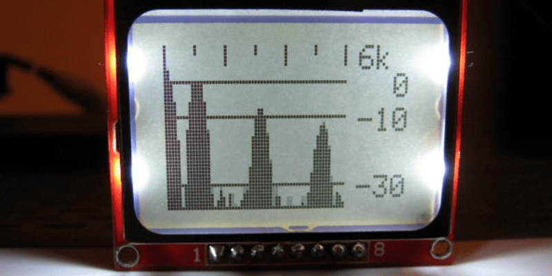
The result isn’t a snapshot of a single moment in time, as it would be with an FFT. For instance, his latest version of the software takes almost 3/4 of a second to take 61 measurements across 500 Hz of bandwidth and push the data out to an LCD screen. That’s too slow for fast signal data, but is just about workable for looking at the way frequency components of a plucked guitar string damp out, for instance.
We’re sure that there’s some version of FFT code that will fit inside these micros and manage to get the job done faster, and if any of you out there can prove it, the gauntlet is thrown. But it’ll take a lot of work compared to just sliding Goertzel’s algorithm up and down, and frankly we just think it’s cool that this method works at all.


Sounds good to me, that was they way it was done before the fft. It was called a bank filter.
It’s also how analog spectrum analyzers worked “back in the war*”: by scanning a range of frequencies by sweeping the local oscillator in a superheterodyne receiver and running the I.F. through a selectable “resolution bandwidth filter”.
* where “war” could mean any war from WW2 through most of the Cold War.
Made me think of the trusty HP 141T or the ALR-20
Yeah, you pretty much read my mind – I have a 140S sitting next to my desk right now (that’s the non-storage round-tube with P7 phosphor, rather than the 141T’s rectangular storage tube) with the 8554B RF section. It’s still a great machine. Never got into airborne hardware, though, so ALR-20 doesn’t mean anything special to me. Up ’til the advent of fairly capable DSP, pretty much everything worked this way. I DID have the opportunity to work with an FFT processor in 1976, though, which was pretty impressive – it was about a $100k machine at the time, compared with $10k for a conventional superhet analyzer.
If by Back in the War you mean today. Agilent has a very good publicly available writeup on the topic. I think it is called, “Measuring Noise with a Spectrum Analyzer” and it details why you would want to use one type of analyzer versus another and why they still sell high end sweeping analyzers in a world of FFT devices. I should warn you though that the whitepaper is about 80 pages and they casually suggest which of their products would be best for each measurement as you read through it.
not quite, the Goertzel algorithm is basically a way to calculate a DFT(FFT) on a single frequency sample by sample when all you need is amplitude
As I recall, it also gives phase.
It does. DFT uses two separate filters, one using cosines and the other sines, to get real + imaginary components. You have to do an additional calculation (sqrt(real^2 + imag^2)) to get magnitude out of it, and another (arctangent(real/imag)) to get phase.
That is making very good use of an tiny85. Very cool!
Interresting!
I must ask, why is an Attiny84 so different from the 85, or is it?
It came out after the 85 and has more pins.
I just want a simple micro for making an IR remote or blink enough pins for a clock.
The spectrum analyzer looks great BTW. Didn’t know that could be accomplished with such a small chip.
They’re pretty different. The first digit(s) is the flash ram, and the last one(s) is a series number.
So 25,45, and 85 are the same pins/peripherals with different flash. 44, 84 are a different series with the same amounts of flash. It gets confusing these days, with the 841 and so on… They’re running out of numbers.
The 44/84 series is great b/c they have a lot of pins. The Tiny45/85s have a high-speed timer/counter that’s PLLed off the cpu clock and can run reasonably fast — which is what makes it useful for bit-banging USB.
I guess I’ll just purchase a few of both then! :)
The comparison charts comparing micros aren’t particularly helpful for a newbie.
Wait, they’re using the highspeed timer to bitbang USB, now? I’ve seen it used for FPD-link ;)
A similar device to the 85 in a higher pin-count would be the 861.
But blinking pins, you’ve probably no need for a 64MHz high-speed timer, nor 3 PWM channels with dead-time generators and complimentary-output. (And, up from there, the AT90PWMx series).
Sure this may be the “wrong way” to do this project, but shows that it could easily handle e.g. looking for a few specific frequencies (DTMF) without the overhead of FFT.
Not only a perty-decent hack, squeezing a lot out of a tiny (memory and pin-count) part, but also a good intro to another tool others mightn’t know about.
Moments like these, it’d be nice to have an edit option… But notarealemail’s point about comparison-charts is a thing. Took quite a bit of time until it came to my attention that one way to look for your needs is to search the header-files for register-names that match your needs: (e.g. you need PLL? ‘grep PLL /usr/lib/avr/include/avr’) But that doesn’t help much for comparing general feature-differences.
Some things, 8-bit processors are just not made for. These days, you can get an ARM-based 32-bit chip for very nearly the same price as an 8-bit microcontroller. It’s really just a matter of choosing the right chip for the job. If you want fast math, you go with the 32-bit engine. But if you want the math to be easy and don’t care too much about the responsiveness of the display, then go ahead and use an 8-bit core. Just expect to live with its limitations.
But let’s assume there’s some compelling reason to use a tiny processor. Maybe power is an important factor, for example. Whatever. Here is something else to consider:
Looking at the display, this appears to be for an audio spectrum, with 100 Hz/pixel horizontal steps. Which is fine if you want the display to be linear by frequency. This is what FFT gets you also, by the way, and it’s not the best thing for a display that’s showing audio information, because our ears do not detect pitch in a linear fashion, but rather logarithmically. So instead of having a display that has a horizontal scale linear in Hz/pixel, it might be more useful to devote a certain number of pixels to each octave. The display is using 60 pixels of its horizontal space for frequency, so you could divide this into three decades of frequency, to get 20 pixels each covering 10-100, 100-1k, and 1k-10k Hz, which you can further subdivide logarithmically, so that each frequency slot is 1/20 of a decade. Alternatively, you could split the band into octaves, and devote each horizontal slot to a fraction of an octave, but it’s a lot easier to label a scale that’s in decades. I didn’t look too far into the Goertzel algorithm (TL:DR), but if I understand it at all, it’s a digital filter you can apply at each frequency, so you could use a table for center frequency and bandwidth of the digital filter for each horizontal step, so that each frequency step only takes the time required for the bandwidth of that slot. This would take more CPU cycles for the lower-frequency slots, and much less for the higher ones. I’m not sure that this would end up more efficient than the linear frequency scale, but I think it would make the display more useful.
In that last paragraph, I mean mainly for the “full-frequency-span” display. Of course, when zeroing in on a signal, you do want linear frequency scale.
Wait, you mean to tell me that faster clocks and more bits gets higher resolution???
Thanks Captain Obvious.
If he used a faster chip (with a floating point unit) that would definitely be NOT A HACK!!1! But yeah, that’s the “right” way that’s inferred in the title. Have 60 pixels, do an FFT/DFT with 64 bins, throw 4 away. Done.
Imagine the headline though: “Engineer Makes Sensible Choice: Implements FFT the Obviously Reasonable Way”. Or if we wanted to go click-baity: “Boring and Appropriate Design Ideas: You’ll Never Believe What Goes Wrong! (Nothing.)”
“Man Sidesteps Challenges By Removing (Arbitrary) Constraints!” Oh I could go on!
A lot of what we post is silly and fun and makes no damn sense whatsoever. Some of it is brilliant. [agp] just wanted to play around with the Goerzel algo and push it to its breaking point. Mission accomplised.
It apparently wasn’t obvious enough to the maker of this project.
you mean the good way.
The maths could be optimised to reduce the loop time. Easy optimisations such as performing a right shift instead of dividing by 2 etc (depending on MSB, LSB etc)
Knowing the chip architecture is very important too. For example, I was using a PIC18F that had a hardware multiplier but not divider. The only two divisions were /10 and /5 which took around 500 clock cycles each. I reduced this to around 40 by having my own helper functions that I could call that used multiplication and shifting to get the right value.
Dividing by 10 was actually multiplying by 103 and shifting 10 to the right (dividing by 1024). Rounding errors appear if your starting value is greater than 178 but it worked in the range that I was looking at.
Again, dividing by 5 was multiplying by 103 and shifting 9 to the right (dividing by 512). Rounding errors appear from 174, but again the largest number I was dividing was 60.
For several years I’ve wanted to make an audio spectrum analyser that produces logarithmic results using digital techniques, rather than analog filters. As pointed out by BrightBlueJim, our ears respond to logarithmic frequency (as well as volume). I’ve been looking at the ‘constant-Q’ algorithm, but I’ve never found an implementation in anything other than Matlab – and I haven’t got my Matlab port for my microcontroller going just yet.
This might take me a step closer… having never heard of the Goertzel algorithm before. The “proper” analysis of audio signals needs low time resolution at low frequencies (slow response) and high time resolution at high frequencies (fast response).
Reading a little on how Goertzel works, I’m taking a guess that to do a proper analysis, a whole stack of parallel Goertzels would have to be computed? Not being a mathematician, perhaps that is what the ‘constant-Q’ is doing anyway…