What’s your favorite value of resistor? 1K? 10K? They’re all fine, but when you need nearly no resistance at all, nothing beats the good old zero-ohm resistor.
Wait a minute! Resistors are supposed to resist current. What the heck does a zero-ohm resistor do? Well, the short story (tee-hee!) is that it’s like a jumper for single-sided surface-mount boards. In the bad old days, companies used to save money by running single-sided boards, and you could buy wire jumpers to help make the layout that much easier.
Fast forward to the modern era, where there’s not a through-hole component to be seen. What’s the resistance (ideally) of a wire? Zero ohms. And thus the zero-ohm resistor was born. We have a whole spool of them in our closet in 1206, the largest SMD size that we use, in order to be able to sneak two or three tracks underneath, even on a home-etched board. They’re great.
Anyway, what set us off rhapsodizing about the lowest value resistor was this article on the peculiarities of the zero ohm resistor. Of course, nothing has zero resistance, and the article walks you through some of their real-world properties. Enjoy!


Damn, there goes my masterplan of soldering a few thousand into a ring for superconducting current storage.
The solder joints would of got you anyway.
*would have
Phase 3, Profit
I work at a place where we regularly deal with sub 10kelvin temperatures. At that level you have to be conscious of solder becoming.
~However, there’s a limit to the current that can flow though materials before they loose their superconducting nature.
That’s okay, could have just put one in parallel across the joint….. hell, one each side just to be sure. ;-)
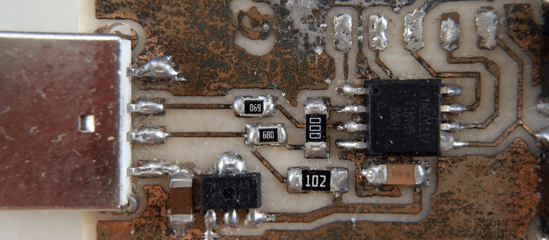
what an ugly board, eroded as hell :)
It’s actually pitted and filled with toner. It’s ugly all right, but it’s been typing my passwords for four years now, and I’ve schlepped it around in my pocket and my bag and… It’s taken a licking, keeps on ticking. No complaints.
But yeah. Optically, she’s no prizewinner.
(Oh, and part of what you think is eroded may be the “G” that I wrote in Sharpie to denote the ground pin on the programming pads.)
Heh, my mental Sherlock was still spinning on what’s got an Atmel and USB and might be frequently carried in a pocket? Because corrosion looked identical to an old phone I varried about 5 years.
Wabi-sabi (侘寂) electronics.
what is it?
Right in the middle of the photo is a 680 in series with a 000. Wouldn’t it have been easier just to bridge the trace with the 680?
“We have a whole spool of them in our closet in 1206, the largest SMD size that we use, in order to be able to sneak two or three tracks underneath, even on a home-etched board.”
Since the 680 is not a 1206, perhaps it was quicker to use a 680 and a 000, both on hand, instead of buying some big 680s?
Good point! And I can’t remember. Maybe I didn’t have the tech/practice at the time to pass a trace reliabily under the smaller (0805?) 68-ohmer?
The pitting in the copper dates the board from shortly after I moved, and had to use a color laser printer which makes for horrible transfers. I was also hitting it with too much heat at the time, in retrospect, so traces got smudged during the transfer routinely. I bet I just didn’t trust myself and didn’t want to do the clean-up.
Technically they are called zero ohm ‘jumpers’ not resistors. As you pointed out, resistors, well.. resist.
https://image.spreadshirtmedia.net/image-server/v1/products/136055828/views/1,width=800,height=800,appearanceId=2,backgroundColor=F9F9F9,version=1478003241/resistance-is-futile-t-shirts-men-s-t-shirt.jpg
I want that shirt!!! ROTGL!!!!!!
no problem, must be somewhere here https://www.spreadshirt.com/resistance+futile+gifts and probably in other places (maybe also eevblog-shop?)
no idea what “ROTGL” means…
Maybe he’s got one of those rustic cottages with pounded dirt on the lower level, so can only roll on the ground laughing, not an actual floor.
Rolling on the Ground Laughing? is that some kind of Ground/GND joke?
Nice! That’s really clever—I’m definitely going to use zero ohm resistors as jumpers on the next board I make. Thanks for the tip!
Same here, I feel stupid for not thinking about it earlier, that’s way better than trying to line up 2 layers.
So, my day job is an engineer for an aerospace company; I’m in the civil space side, developing and testing weather satellites. For the last month, I’ve been troubleshooting a flight card that’s going into a module scheduled to fly in 2018. The module was designed in 1997, with the last design changes taking place in 2009 due to EOL on certain parts, one of them being the main communications protocol chip.
First time testing with the new chip. Board fails. Can’t establish communication with the test PC. Contact chip manufacturer; this is listed as a “drop in replacement”. Vendor looks at our schematic. “You’ve got a 4.7K Ohm pull down resistor on those two pins. I’ve seen this before; there’s some leakage current created, and it’s spoofing logic high. Swap that out for a 0 Ohm resistor and see if that works.”
Have a tech short the resistor pads on the engineering board. Holy shit, it works.
0 Ohm resistor new favorite resistor.
Well I can’t say I know everything, but 4.7K for a pulldown would have made me scratch my head in the first place, would never think of using more than 1K for anything I actually wanted to pull down.
Huh? 4.7k is “the” standard value for pulldown resistors. Depending on the kind of signal and logic device, I’ve even used values up to 100k.
4.7K is a pull *up* value.
Please expand on that… Why have different values for pull up or pulldown resistors? I also always thought 4.7K was *the* standard value.
With the exception of CMOS, Vih is further from Vcc than Vil is from ground.
The article is about a chip that has been re-run to be a drop in replacement for an older chip. Older technology required lower values (generally) and also has asymmetric input characteristics. An example would be the original TTL technology that had a higher offset current so a pull *up* was around 4.7K and a pull *down* was about 330 Ohms.
Newer technology such as micro-controllers have very high and symmetrical input characteristics. For example the internal pull up resistors on an ATmega328p-pu such as used on the smaller Arduino’s is in the range 20K to 50K. I can’t right now find the input impedance but from memory it’s in the order of 100’s of K.
If you are using through hole resistors that are very much inductors in the way they are LAZER trimmed then the a lower value would more for shunting any voltage that may be induced into the ‘inductor’.
ok, I found the input impedance. The reason I didn’t find it before is that it’s specified as a leakage current of 1uA for an I/O pin with a Vcc of 5.5V and that comes to about 5.5Meg Ohms.
@RÖB:
“with exception of CMOS” :-) I would consider CMOS as the standard of today’s electronics. So very often the logic threshold lies in the middle.
Do you own shares of the power company? :-)
Or worse a battery manufacturer?
4k7 already wastes 1mA (@5V) I mean, of course it depends on voltage levels and required speeds and sometimes it is necessary to go that low.
I always use 10Ks for pullup or pulldown. I have no rationale. Except on this one battery-powered radio switch, where I used 1M b/c anything else would screw up the battery life.
Ah, the liberties you can take with one-offs!
I’d be careful about using a 0 Ohm resistor on a non-power pin of an IC as it can result in the impedance to ground being lower than a power pin and that may effect noise immunity. It’s not a common problem due to chip design but when it does happen you will be looking for a long time to find it. 5 – 10 Ohms would be a better choice.
My favorite resistor is 1.1k 1/4watt.
About 1976 I got a bag of them still in packages, for a couple of dollars at a hamfest. From a well known US company, not cheap imports.
Perfectly useful for any time I needed a 1K resistor. And they had long leads, unlike the resistors I pulled off circuit boards.
I still have some today.
Michael
I got a killer deal on 200 1.2k resistors a few years ago.
I have some 0 ohm resistors in the standard 1/4 watt style package in my resistor box, snagged from an old stereo amplifier that had been in a flood. It has a single black stripe, and I’ve wondered what I was going to do with them.
Yeah, I have some myself. Nothing beats that sexy stripe. Never used one yet, maybe for some art project one day.
I use them as arms on my Electro-Man earrings :)
I use them for exactly the same thing as in this article, jumping traces in a straight line on single sided home etched PCBs. Really just an aesthetic, I prefer the look of a “resistor” than a bit of wire, but it’s also a little easier to insert, and the body holds them off the traces if you are “top side soldering” and trimming the legs flush with the bottom for a flat surface.
I’ve seen many 0 Ohm, 0%, 1/4 watt leaded resistors, well at least the color code seems to indicate that : black – black – black – black
The company I work for uses them as voltage selectors in power supplies. All three for 120, these two for 240, etc. Default at 120 for initial test (of the partially assembled instrument) then modify if needed for the burn in and final test.
I saw the through hole variety in TV’s first. When sets were made for different countries with different transmission standards then the 0 Ohm resistors were to select the attributes of that region so that *only* the Bill of Materials need to be changed rather than the whole schematic and circuit board.
I’ve always been a bit perplexed on how to calculate the required power rating for a zero ohm. ;-)
Even more confusing is the percent tolerance on the zero ohms. Can I have a negative resistance?
It’s easy, (actual – nominal) / nominal.
I think your formula is broken; I keep getting 255 regardless of the measured value.
By that equation, I have a really small number on zero… I should in theory have a ∞W resistor…
They have rated current tho. 1206 is good for about 2-3A or so.
Depends on the resistance :-)
Once I got offered some types which only guaranteed <50mOhm. A calculation showed, that they are not good for more than 2A at higher temperatures, in a 2512 package. But they exist as solid copper variants, good for 100A
Be careful when buying them: Be sure to take the 1% version, don’t be fooled by the worse 5% version!
I got some 50% dirt cheap from Elbonia, I figure 0 * 1.50 = 0 still :-D
it seems like the resistor in the picture is a “bridge” over a trace.
is it safe to use it like that? no real chance of shorting out with trace underneath?
They are made just like normal smt resistors and the bottoms are non-conductive.
That’s kind of the whole point of them, otherwise if the traces were next to each other why would you use a 0 ohm resistor instead of just having the traces connect? ;P
sometimes you do some hardware configuration with the resistors, I have also seen optional antenna filters (in the GSM world) where the inductor is shorted with a 0ohm resistor.
Like a bridge over trouble traces?
No, they are ceramic underneath, at least the normal thick film type
They are also used as configuration jumpers and to isolate sections for individual test (installed after testing).
I was looking at a dev board the other day, and it had all of these unpopulated 2-pin x whatever headers. Schematic shows them as configuration jumpers. Flip the board over and there are tiny (0405?) 0-ohm resistors bridging the through-holes instead of jumpers.
That’s brilliant, though, for piecewise testing. I’m going to have to remember that.
Yes, I had a project were the EE guy had masqueraded the thing in a clever way: each sub-system had a PI filter on its power line. So when you debug you can isolate the subsystems by removing the inductor, but in production you don’t really have to populate the PI filters if you see they were not necessary, you can use 0 ohms jumpers. No respin.
Yeah, that’s what I came here to say: we put them all over the place for isolation of circuit groups on power-up, and most of our ATE boards have banks of unpopulated 1206 spots that we populate per-board so the ATE’s can identify which board is being used. It’s a lot easier than a serial eeprom.
A while back I ordered a batch of 1206 0-ohm resistors from Digikey and they instead sent me a batch of 500mA fuses. I was sort of stuck on how to reply, because, well, they’d work just fine so they weren’t the wrong part, but they weren’t the right part either.
Two more on my current board: it has three power inputs, one for logic and two for power amplifiers that the logic controls, so you can guarantee the logic will stay alive even if an amplifier shorts. On the eval board, for ease of use, we load 0 ohm resistors bridging all three supplies so you can get it working with just one supply. Likewise, the intent is for a uC on the same board, with short traces to the chip. If the uC is somewhere else with long traces/off-board we provide footprints for rc filters, but bridge them with zeros for usage.
Oh, and on my ATE boards that are doing high precision current measurements I often put down four footprints, two series two parallel, to allow me to load resistors to get exactly the sense value I want. If I get lucky and find the right resistor, I stick a zero in series with it (and hope it’s actually zero, but that’s what four wire resistance measurements are for.)
This thread is why I like Hackaday.
I recall the first time I saw them in an Otari MX-5050 eight track reel-to-reel tape machine. 1/4 watt resistor beige package with one black stripe as mentioned above. What is that? Measured it, zero ohms. We just started laughing.
Yah, must admit on first encountering them in the 90s, I was thinking it was some engineering easter egg joke.
As far as i know these resistors exist because the assembly machines (for THT) can’t handle pieces of bare wire.
I was just wondering if there is an infinity Ohm resistor avaible somewhere?
Of course, but they are delivered in two pieces ;)
Actually.. the linked article talks about a company using 0Ohm resistors with no markings in various colors at pointless places to discourage reverse engineering.
So maybe some company is using fake infinite resistors too for such purposes, put traces and place a part with only soldering pads and no internal connection.
Ran into a reel of them once in a “spares” bin-referred to them as “encapsulated short circuits”.
I use them as net ties. Because net ties are evil.
They are also useful for (low precision) current sense resistor and as a fuse.
Just because they have a current rating doesn’t mean they’ll work as a fuse. If you need a fuse (for e.g. UL / safety / legal compliance reasons) then you need to use a fuse.
Knock-off Pololu A4988 stepper driver modules use these for the current limit sense resistor, and it’s not uncommon for the IC on those modules to give up vital smoke.
Alarmingly I’ve seen them be used as fuses in E-POS equiptment. Even ferrite beads purposely undersized to act as both a fuse and an emi filter.
Though no-one hotswaps in the feild anymore, we did have a unit come back once where the daughterboard literally was charcoal!
The daughterboard supplied power, touchscreen and display data to an operator facing display.
However the cause arrived later: a (mini-SCSI like) cable badly frayed, cut and burnt.
Lesson: NOT A FUSE!!!!!!!!!!!!!!!!!!!!
These resistors are also super helpful when creating a new circuit you’re not entirely confident about.
Ex: creating an RS232 line and concerned there may be ringing? Throw a 0 Ohm in and swap it with a “real” resistor if problems arise.
^this x10^
New designs, early prototypes, still playing “what if”. Just sprinkle them around the board anywhere there’s even half a chance it might be useful later.
Then I have a favorite trick of using a pair of them “just so” in the TX and RX lines of serial connections. With a bit of forethought, two of them side by side can be used to reverse the RX and TX connections (horizontal vs vertical).
I just did the RX TX thing on a prototype board. Had to make a note on the silk screen for the next guy.
You’re wrong, you’re all wrong. It’s the ultimate current sense resistor. Read all about it when my Kickstarter launches for the erizer.
on my project audio preamp, I have output op amps that can run in unity gain mode. if you want gain, you put in a 1k or 10k or etc (and the matching front-end R’s too); but if you want unity gain and you have smd pads on the board, you use a 0 ohm R. I bought my first bunch just a few weeks ago, in fact. previous board rev allowed for gain but I wanted to configure this build for unity gain. ugly way: cutoff leads from TH parts as bridges between pads. but the 000 looks a lot cuter on the board than the hacky wire ;)
Couldn’t a zero-Ohm resistor be used as a simple type of thermal sensor? Increased heat, increased resistance.
That makes zero sense.
You.. well done :)
Zeroes have been around for awhile. Found them on boards made for the HP2100A minicomputer in the early 1970’s, in 1/4 watt thru-hole form factor long before SMT was even envisioned. And those were double sided boards…
Thank you for pointing this out. I read this and was going “Huh? Zero Ohm resistors are a surprise?” We had HP and the board jumpers were these.
yup, the old zero ohm joke, from before surface-mount existed, if you want to divide by zero you do with analog and solder a zero ohm and divide by zero, unfortunately it always results in a damaged component or shorted powersupply
Well if you get a 1v supply and a zero ohm resistor then mathematically you get infinate amps.
if you then take infinate amps and pulse a transformer with it then you should get infinate voltage minus losses (still infinate).
Infinate voltage and infinate amps give infinate wattage.
Ssh, keep it secret. We don’t want those over-unit guys figuring that one out now do we?
Logic of the above was based on the word-play joke of a guy breaking out of prison with only a chair.
I just love reading short stories.
How I lived till now without knowing how much is useful a 0 ohm resistor!
-single board bridges
-the “not sure what resistor or cap to place” placeholder
-easy to test probe
-a one time switch to repurpose a board
-machine placeable wires
-reverse engineering mines when camouflaged as other components
-reference for testing other resistances
-cheap for testing a oven setup
-joke with other engineers
-projectiles for mini railguns
And embedded in black powder rocket engines, for electric launching.
Make sure you get good 1% metal film 0 ohm resistors with a low tempco!
They are also useful as jumpers for things that the user won’t have to change. You can change jumper settings by flipping a bit on the pick and place machine, which is cheaper than through-hole jumpers (requiring manual insertion) and doesn’t require throwing out your PCB inventory for minor changes.
Resistors of a value <0 ohms would be very useful.
There isn’t enough market for them to be produced as stand-alone units. You have to roll your own.
(hint: op amps)
Quote: “Of course, nothing has zero resistance”
What about the negative resistance used in a Chua’s circuit for a chaos oscillator 99?
These are also used as the primary component of black-noise generators.
I had a very old (70s, maybe early 80s) Weather Radio. It had a circuit board, but everything was hand soldered on or through the board.
It died, so I took it apart just to look around. It had a zero ohm resistor in one spot where the wire was cut too short. The resistor had that extra inch of contact so that it could be soldered together. The chunky portion of it was actually fitted into the board.
I need infinite ohm resistor
Place contact A at centre of known universe… place contact B in PCB…. start walking away from contact A…. stop when your resistance is as close to infinite as you require.
^ ahahahaha
wouldnt a 6 amp fuse wire work or a solder bridge?
Some ham transceivers use tiny resistors, zero ohm or not, for configuring gear. Clip the right ones, and your ham-band-only radio can transmit elsewhere in the HF spectrum, including marine radio frequencies. In a pinch, your ham radio can double as a far more expensive marine radio.
Started doing this when I started doing toner transfer surface mount boards — no drilling for jumpers!
On the topic of through-hole 0R resistors, there are commonly two types: one where the body is a ceramic slug flashed with carbon or metal film, just like a regular resistor, and ones where the body is a slug of metal (usually copper or something ferrous, I don’t know if it’s steel or iron or what). These are great for wire lead legs on little modules, especially if you can source the metal-body variety — the leads become the current limit.
Sometimes called a “machine insertable jumper.”
I work for a low to mid volume EMS (electronics manufacturing service) provider (also called a contract manufacturer) and I did a quick system check. We currently have 18 active part numbers for various 0 ohm resistors totaling a qty of almost 160,000. All but 3 are SMT and range in package size from 0402 to 1206.
I sometimes use 0.5 ohm resistors as jumpers for SPI lines to EEPROMs. its really helpful when laying single side boards… and looks a whole lot nicer than a wire jumper…
Don’t forget though, that if the application truly requires a fuse, you should use the proper rated fuse…
http://images-cdn.9gag.com/photo/a9M9BGL_700b.jpg
In our voltage distribution units, even a shifting spanner is a fuse. It’s rating is about 3 sticks of Gelignite and has the added feature of dismemberment.
In a past life I worked at a computer manufacturer. The company that designed our motherboards would put zero ohm resistors in all the data lines for serial, parallel, front panel audio, and PS2 ports, back when motherboards still had these. We would send the board out for FCC testing, fail, and start replacing zero ohm resistors with ferrites instead until testing passed. Why not just put in the ferrites in the first place? They cost a lot more than zero ohm resistors…
I thought, this zero ohm resistors get replaced with series termination (several 10s of ohms) resistors if necessary.
That could be. It’s been a lot of years since I worked there and I don’t really remember the details.
I build lots of stuff on single-sided Perma-Proto boards and find 0Ω through-hole “resistors” to be very useful as jumpers (easier than bending a piece of wire to the right length) to the power traces or to cross the center divide. They’re super cheap from China, much cheaper than pre-formed jumpers.
I remember being told zero ohm resistors, in small enough size, went INSIDE a via.
The story being: the track inside the via acted as an inductor at RF / microwave frequencies, and the resistor helped cancel that out.
I never ended up working with RF that high, but I remembered the story.
Confusing story but the size of the holes in the view window of a microwave oven will give you an idea how how large a hole can short out (or reflect) microwave energy. You wont get microwave energy through a hole the same size or smaller so you can forget sending a microwave signal through a via.
You will see that in all of the high frequency PCB antennas that they are on one side only. I via is a reflective stub that will reflect most or all of the microwave energy.
Can we just use a wire as a jumper ?!