
If you’re into anything even vaguely mechanical on the broad hacking spectrum, you’ve come into contact with things that spin. Sometimes, it’s important to know precisely how fast they are spinning! When you’ve got the need to know angular speed, you need a device to measure it. That device is a tachometer. And the most useful tachometer is the non-contact photo-tachometer.
The basic principle of operation of a photo-tachometer is quite simple. The device contains a light source – typically a laser, which can create a focused, coherent beam of light. This beam of light is capable of bouncing off of reflective objects.
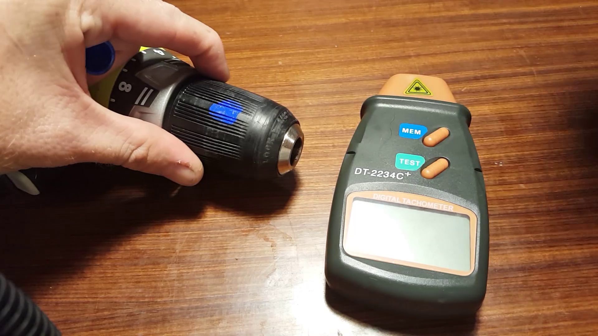
To use the photo tachometer, you start by creating a reflective mark on the rotating surface you wish to measure. You must also ensure the rest of the rotating surface is comparatively non-reflective. An easy way to do this would be to create a white spot with a paint marker on an otherwise black or dull-metal shaft. Then, aim the beam of light from the photo-tachometer at the mark on the spinning shaft. Each time the reflective spot passes the beam of the photo-tachometer, some light is reflected back towards the device, where it is picked up by a light sensor. By counting the number of times the light sensor is triggered in a given time, it’s possible to determine the rotational speed of the machinery under test.
For example, let’s say we have a motor spinning at 1200 revolutions per minute. We aim the photo-tachometer’s beam at the white spot we’ve marked on the motor’s shaft. Let’s assume the photo-tachometer counts the number of pulses it sees in a unit time of one second to make its measurements. In one second, the white spot will pass the beam twenty times, triggering our light sensor as it goes by. The microcontroller in the photo-tachometer then does some simple maths – twenty pulses in one second, multiplied by 60 seconds – and we get a rotational speed of 1200 revolutions per minute on the display.
It is easy to imagine that if our shaft is rotating much more slowly, on the order of 10 RPM, our photo-tachometer will only see one pulse every six seconds. If we up this to 12 RPM, it’s still only one pulse every five seconds. Our tach is going to suffer trying to measure such low rotational speeds and it’s going to take a long time for it to notice any changes. Is there anything we can do to help in this situation?
Why yes, there is! We can place additional reflective spots on our rotating shaft. Let’s put ten spots on our rotating motor shaft. Now at 10 RPM, we’re getting a pulse of light every 0.6 seconds, and at 12 RPM, every 0.5 seconds. Our tach is now able to much more quickly respond to changes in speed at the low range – and we just need to remember to divide the display speed by ten to account for our additional markers.
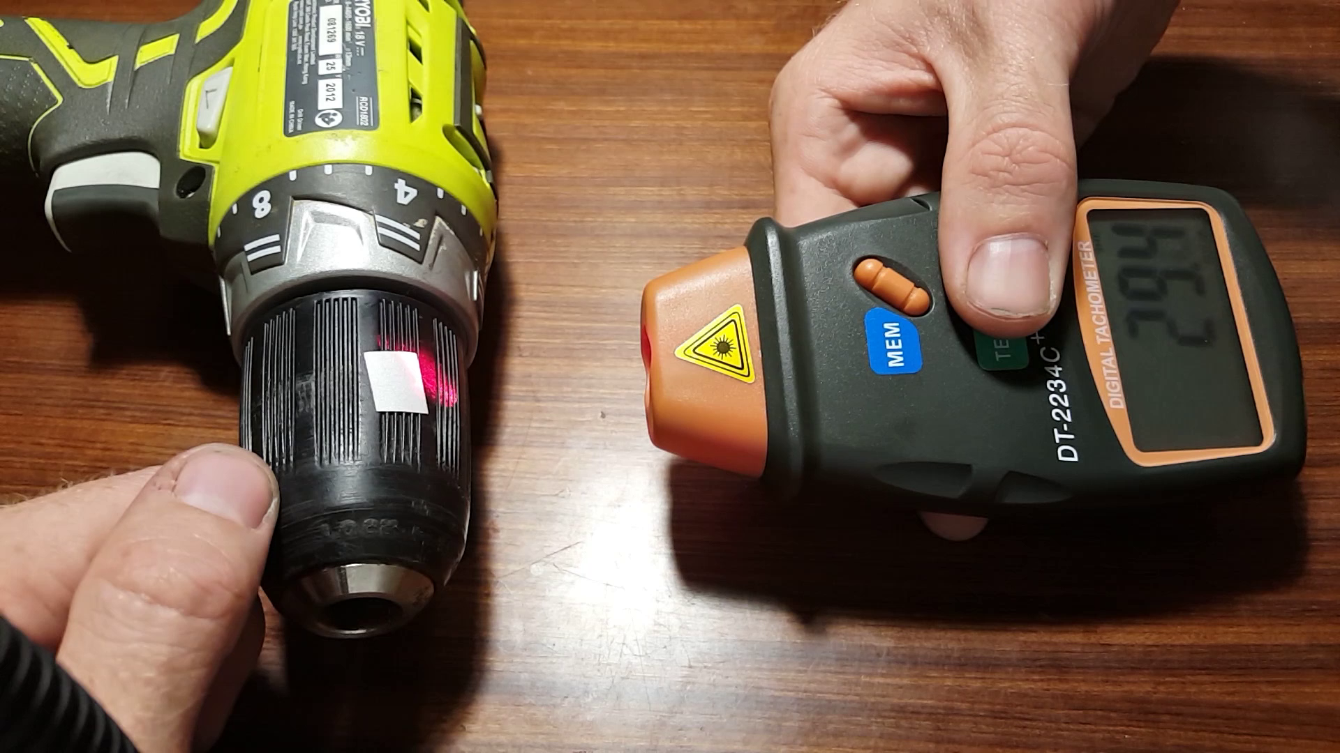
There are other tricks you can use to improve performance, too. Many photo-tachs come with a supply of retro-reflective tape in the box. This is a special tape filled with lots of microscopic glass spheres that allow the tape to reflect light at any angle. Using this instead of white paint on a rotating machine allows us to measure with the photo-tachometer at an angle other than perpendicular to the marking. I used this myself to make a measurement of my car’s engine speed. It was impossible to point the tachometer straight at the crankshaft – but with the retro-reflective tape, I was able to point the laser at the crank pulley from above at an odd angle and still get a good reading.
The real power of photo-tachometers is they make it easy to get accurate rotational speed measurements without having to make any major modifications to the machinery beyond a spot of paint or tape. It’s a great non-contact method of measurement, and a usable photo-tach can be had for under $20 on eBay. I’ve wrapped up a review of the DT2234C+ tachometer on YouTube for your consideration. It’s the kind of thing that you’ll find incredibly useful having stashed away in the back of your toolbox. You’ll never know when you need it!


I got that same unit, I think from DX or something for a few bucks… Thought it would be a useful tool but I don’t think I’ve actually had a need for it yet… The one I got came with a bunch of reflective tape… I was pretty sure how to use it was pretty self explanatory though…
next up, how to use a ruler!
Next up, a tutorial demonstrating Mr. Smarty getting his knuckles whacked with said ruler. And before you ask, it will be an Imperial ruler. They hurt more, by a significant fraction.
Because in addition to the physical pain you’re also hurt psychologically when you see non-metric units on measuring equipment. ;)
Thats the worst pain, seeing non standard measuring equipment way into the 21th century…
Yeah, I mean it’s self explanatory if you’ve heard of one before. There’s always going to be plenty of people who are like, “OH MY GOD, this solves the exact problem I’m having!” and this one’s for them.
Yup. I would enjoy another article about calipers, because I keep seeing people using them incorrectly.
yup it is. Hadn’t been in the nook of the internet where this was explained, so that’s a nice little trick to store in one of the nooks of my brain until I need it.
Making a tach using scrounged parts would have been more interesting. Especially if it measured small variations in timing, to report subtle variations in speed, or cogging in the motor. That is a concern on some devices where smoothness is important (like lathes).
Yea but if someone did it, they would probably use an Arduino. And it would be limited by the 100 microseconds to read a value from the ADC, so it would have an upper limit of 600K RPM, well half that – so 300 RPM. And then there would be the whole argument about it not being a hack because an Arduino was used.
300K RPM not 300 RPM
I’m pretty sure if one searched through the hobbyist electronics book archived on the web at least on project for a Tach that use reflected light pre inexpensive lasers and micro controllers. Og course “real” hackers ignore an prent hazards and use a contact tach.
Humm same kind of instrument in Ali are almost half the price ( around $9 USD ) http://s.click.aliexpress.com/e/Jq7EUnI
Blue is the worst possible color to use to reflect a red laser. That laser is probably 650nm, and the blue paint absorbs that probably almost as well as black plastic. Try red paint. Or nail polish.
Now that should have been obvious! Blue was the choice as it’s literally the only paint marker I have on me but yes, red would likely have been better. Liquid paper would have been good too.
There’ve been times when I’d rather not go where the measurement was being made, in case the rotating object flew apart (which it sometimes did). For those cases, I modified it so that the on/off switch is at the end of a longish wire. In one case the display wasn’t visible, so I placed a mirror in front of it and angled the mirror to reflect it to where I could see the reflection (I know, I should have hacked the display too and put that on the end of long wires too :-)).
I do this with a photo diode hooked up to my mic input on my laptop and any free sound card oscilloscope software. Much easier and depending on the software you can detect fine variations/instabilities. If you have a really good sound card you can measure up to 96,000 RPM.
https://podfeet.com/NosillaCast/NC_2007_08_26/vib_tach_1.jpg
That’s how I measure RPMs.
Quick, easy, surprisingly accurate.
No dead batteries!
So, apparently you stick it onto the engine and then move the slide until the wire is vibrating as crazy as it can, then do a little math.
Very nice! Never seen that before. :)
So I guess these could not be used on gas powered hand tools like leaf blowers or string trimmers or lawn mowers ?