[Pete Juliano, N6QW] built a 20 M QRP CW transmitter using just a handful of parts. That in itself will not raise any eyebrows, until you find that he built it using one of the very first RF transistors manufactured all the way back in 1955. That’s from before the time most of us were born and not many years after the invention of the transistor in late 1947.
![]()
QRP in HAM-speak technically stands for a request to “reduce power” or an offer of “should I reduce power” when appended with a question mark. A QRP transmitter is designed to transmit at really low powers. The accepted upper power limit for QRP transmitters is 5 W, at least for modes like CW using FM or AM modulation. [Pete]’s interest was piqued when he read about a 10 mW 10 M QRP transmitter design in a vintage Radio magazine from the late ’50’s and decided to replicate it. We aren’t sure, but it appears he had a Philco SB-100 RF transistor lying around in his parts bin. The SB-100 was one of the first surface-barrier transistors and could output 10 mW at frequencies up to 30MHz.
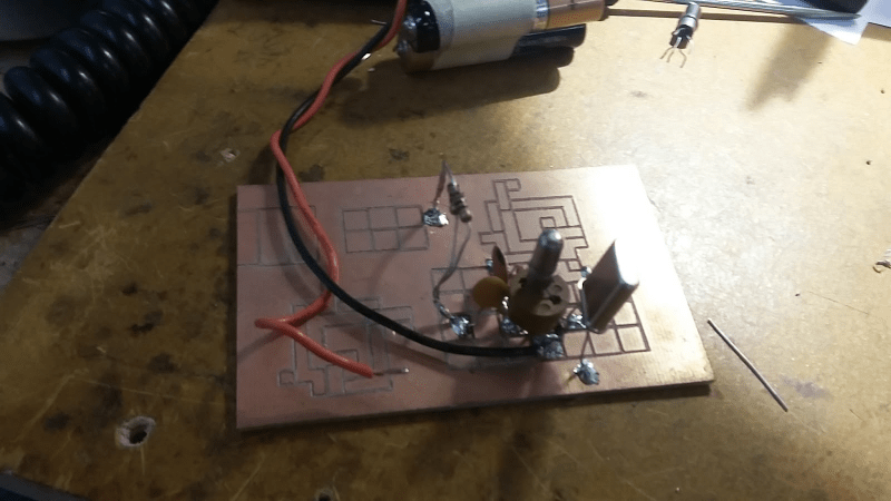
[Pete]’s rig was originally putting out 0.4 mW with a 3 V supply, and oscillating at 14.060 MHz in the 20 M band. The design appears to be a simple Colpitts oscillator with just a few parts assembled in dead-bug style on a piece of copper clad laminate. After adding an output transformer, he managed to increase the power output to about 25 mW. Check out [Pete N6QW] sending out a CQ shout out from his QRP transmitter in the video after the break.
If this gets you interested in Amateur Radio, but you are mic-shy, then [Dan Maloney] has some options for you in Shut Up and Say Something: Amateur Radio Digital Modes.
SBF image via Historianbuff CC-BY-SA 3.0, Public Domain
[via Dangerous Prototypes]


Hack of the day right here. Taking a part and using it for exactly what it was designed for…
Looking forward to your offer of a better hack.
62 years after it was first manufactured.
It took a long long time and he still failed at procrastination!
Good project with a hi-story to tell.
I like Manhattan style PCB builds but wow that PCB looks like “Etch A Sketch meets FR4”
I’m sure somewhere is a datasheet of this transistor that states “not recommended for new designs”
…but will still infuriatingly appear at the very top of Farnell part searches.
Yah, that reminds me… If I do anything really clever, I should stick in one of my stash of OC71s right at the heart of the deep magic and watch eveyones head explode.
OC71s! My first OC71 build was in the 60s. A single transistor headphone amp for a crystal set to listen to John Peel on Radio 1. I think I used a circuit from “Practically Wireless” or some such mag. Had to save up some pocket money.
This is a very clever build. I never got to the stage of build in transmitters.
My first headphone amp for a crystal radio was made with a CK722 in the 50’s. I remember the first article in Popular Electronics on how to build a transistor CW transmitter.
That would be epic.
OC71 = built-in low pass filter and noise generator! How’s that for 1960 tech.
ROFL, yes we had the most advances tech!
I built a 4 transistor AM transmitter using OC71 / OC72 when I was about 7 or 8 years old. I used to scrape the black paint off and in some you could see the actual transistor. I wish I still had some now to use in some circuit for the *bling* factor.
Damn, just googled them for the first time in years….. I need to round up, inventory and test every last germanium transistor I’ve got, and set up a fuzz box production line…
Yeah that part is interesting. Transistors have lifespans orders of magnitude better than say a vacuum tube.
Back before we were saturated with communications it would have been pretty amazing to sit in your room late at night and make contact with someone
I find it pretty amazing to sit in a room and have nobody bug me by various channels.
This is a beautiful Hack. Reminds me when as as a 8th grader with a Tech license I got a nasty 1300 volt shock from a power supply on a tube rig I was building. My Dad said “that was the last time I did a Dumb-ass thing like that!” Right! It was 2N3553/2N3866’s after that. Solid-State!
Looks lush, what is the name of the PCB gouging technique.
Recently fascinated by various PCB designs loving Manhattan style.
As impressed as I am about him having used the vintage transistor, I’m even more impressed by the quality of the lines on the board! That’s awesome.
All of mine come out looking like some clumsy oaf tried to cut the copper out with a utility knife. Might be because some clumsy oaf tried to cut the copper out with a utility knife.
“Power” tools can help significantly here… A Dremel with a tiny ball mill does wonders. You just have to be careful to not snap the ball off…
Pete uses a CNC router to create his PCB’s.
At first I thought he must have been feeding steroids to his Etch A Sketch.
Way back in 90’s I did same type of board using a tool similar to wood carving chisel. My dad made it for me from used lathe tungsten tools. Not easy to carve out the cooper but for very small projects was quick and dirty hack.
What’s a CW?
https://en.wikipedia.org/wiki/Carrier_wave
This has become ambiguous in recent times.
The Wikipedia definition that [RW] posted comments on modulating the “Carrier Wave”.
In old terms “Carrier Wave” (abbreviated to CW) was a definition of a specific transmission mode where *only* the Carrier Wave was sent and it was sent without any frequency modulation – just the Carrier Wave *only*. This was done under the control of a Morse key in Morse code (by simply turning the Carrier Wave on and off) in the earlier days and then later it was controlled by a TeleType relay (TTY).
In the above Wikipedia link the text refers to modulating a “Carrier Wave”. This was never said on older days to avoid confusion with CW so we always described this as modulating a carrier *frequency* and it was completely unrelated to CW.
To add to this confusion there is also a newer term called “continuous wave” here –
https://en.wikipedia.org/wiki/Continuous_wave
which talks about CW as well.
So the best explanation that I could offer (and this is open to correction) is that when you see the abbreviation CW then it refers to the transmission mode that I described here but if you see “carrier wave” then the meaning is ambiguous so you will need to see the context of the rest of the text to determine what was meant.