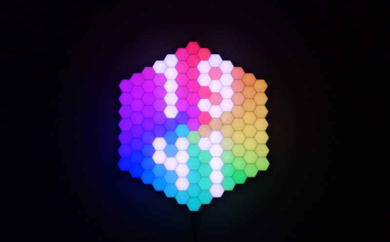
Who says a clock can’t be both useful and beautiful? That seems to be the big idea behind the lovely little HexaClock from [Bulduper]. And boy, is it both.
Probably the most important part of this well-illuminated clock is the light sensor, which allows it to adjust the brightness automatically. If you’re not into that, well, there’s a really nice web app that’ll let you program the dickens out of it.
The brains of this thing is an ESP8266 on a custom PCB which controls the 127 individually addressable RGB LEDs. The clock may look large, but the big printed parts just fit on the bed of a Prusa i3. [Bulduper] used ABS because the LED strip and the PCB might get a little warm; they didn’t want to risk using PLA and having it turn into a Salvador Dali clock (although that could be cool).
Speaking of heat, make sure to use 18 AWG or thicker wires as [Bulduper] advises. LEDs may be efficient, but this clock uses lots of them! If you want to build one of these to bathe your wall in useful light, everything you need is available on GitHub. Watch HexaClock do its thing in the brief demo and walk-through video after the break.
If this is a little too bright for your tastes, check out this synesthesia clock.


That’s a nice clock.
Small improvement, you put all the sections of LED strips in series (at 02:02 into the video). Long led strips tend to have a voltage drop due to the current to all the LED’s, and sometimes this becomes visible. You can prevent this by tapping of Power and GND for each section directly from the power supply.
This also allows for thinner wire for each section, which is easier to solder to the sections of the LED strips. Near the power supply you can put a simple Vero board / strip board to split off all the power and GND wires.
Something is amiss. The numbers in the image are not lined up evenly.
This is very cool. He should consider productizing it. I bet it would sell.
On the power requirements. I’m wondering something, everyone everywhere always quotes the 50 or 60mA per LED max. However, I just powered 50 leds on full white from an USB port, and I somehow doubt that my USB port is delivering 3A of power…
@Daid said: “On the power requirements. I’m wondering something, everyone everywhere always quotes the 50 or 60mA per LED max. However, I just powered 50 leds on full white from an USB port, and I somehow doubt that my USB port is delivering 3A of power…”
I routinely run fairly efficient LEDs with as little as a one or two milliamperes forward current and they are perfectly visable indoors in a normally-lit room. It all depends on how efficient the LED is, the LED color (some LED colors are more efficient; the human eye is most sensitive to yellow-green), and the LED’s effective aperture (radiation pattern or viewing angle).
Just a quick stab:
https://www.digikey.com/en/products/detail/w%C3%BCrth-elektronik/151033RS03000/4490003
Price: Qty.-1, $0.18 USD ea.
Manufacturer: Würth Elektronik
Manufacturer Product Number: 151033RS03000
Description: LED Red Clear 3mm Round Through Hole
Peak Wavelength, λ Peak, If=20mA: 628 nm (Red)
Dominant Wavelength, λ Dom, If=20mA: 621 nm
Luminous Intensity, Lv, If=20mA: 2600 typ. mcd <= Bright!
Forward Voltage, Vf, If=20mA: 2.6 V typ.
Spectral Bandwidth, Δλ, If=20mA: 15 nm typ.
Viewing Angle Phi 0°, If=20mA: 30°
60mA is the old, original, 1st gen WS2812 max sink – for all R/G/B channels at 255 – sinking 20mA each.
I think the b sinks maybe 10-15mA per channel, and the 2020-sized b is down at some 5-7mA per channel.
While there’s very little human visible reward from driving over say 60% (from our non-linear response), and gamma will bring overall current down even more – I think I know why there is still this “point of note” that gets thrown about…
The first gen ws2812 parts (with the 60mA peak draw.. 61mA with the driver not clocking away…) would power on with all the drivers set to max – you’d get this overwhelming *flash* of the entire array coming up as full white – before the internal logic reset.
That was a real issue on one of my larger scale designs.
Pixels have come along quite a bit since that chipset..!
What you are experiencing is voltage drop:
Yes, it’s about 20mA per color so 60mA full white, but at 5V. What you are experiencing is voltage drop to probably 4.5V, being highly non linear, consumption is probably half at this voltage, check with a voltmeter at the last LED pins.
While I believe you’re mostly right about voltage drop being the key issue… how exactly is it “non-linear”? Ohms law doesn’t have any power terms.
LEDs are not linear, unlike ideal resistors.
That’s not how it works. It’s not the LED’s that matter here, it’s *the resistors and the wires they’re connected to* that follow ohm’s law. Oh, and the internal impedance of the voltage source, that acts like a separate series resistor. Those will exhibit a linear increase in voltage drop as the current draw increases.
The problem is actually the vague use of the word “consumption” here. If it’s referring to current draw, that’s entirely determined by the led voltage (which is fixed) and the series resistance. That’s wholly linear. If they’re talking about power, then at least that has squared terms in it, but it’s not really saying much useful in context (since we don’t care about power, we care about brightness). If they’d talked about *efficiency* then it’d be pretty much true, since LED’s have a non-linear efficiency curve *and* our vision is also logarithmic.
Another clock sans seconds.