Vintage Philco Radio Looks Stock, Contains Modern Secret: A Raspberry Pi

Antique radio receivers retain a significant charm, and though they do not carry huge value today they were often extremely high quality items that would have represented a significant investment for their original owners. [CodeMakesItGo] acquired just such a radio, a Philco 37-11 made in 1937, and since it was it a bit of a state he set about giving it some updated electronics. Vintage radio purists, look away from the video below the break.

Stripping away the original electronics, he gave it a modern amplifier with Bluetooth capabilities, and a Raspberry Pi. Vintage radio enthusiasts will wince at his treatment of those classic parts, but what else he’s put into it makes up for the laying waste to a bit of ’30s high-tech.The original tuning dial was degraded so he’s given it a reproduction version, and behind that is an optical encoder and two optical sensors. This is used to simulate “tuning” the radio between different period music “stations” being played by the PI, and for an authentic feel he’s filled the gaps with static. The result is a functional and unusual device, which is probably better suited than the original to a 2019 in which AM radio is in decline.

If you think of a high-end set like this Philco as being the ’30s equivalent of perhaps an 8K TV set, you can imagine the impact of AM radio in those early days of broadcasting. We recently took a look at some of the directional antenna tricks that made so many AM stations sharing the band a possibility.

Continue reading “Vintage Philco Radio Looks Stock, Contains Modern Secret: A Raspberry Pi”

Cloning Knobs For Vintage Testing Equipment

Knobs! Shiny candy-colored knobs! The last stand of skeuomorphism is smart light switches! Everyone loves knobs, but when you’re dealing with vintage equipment with a missing knob, the odds of replacing it are slim to none. That’s what happened to [Wesley Treat] when he picked up a vintage Philco tube tester. The tester looked great, but a single knob for a rotary switch was missing. What to do? Clone some knobs! You only need some resin and a little bit of silicone.

The process of copying little bits of plastic or bakelite is fairly standard and well-tread territory. Go to Michaels or Hobby Lobby, grab some silicone and resin, make a box, put your parts down, cover them in silicone, remove the parts, then put resin in. For simple parts, and parts with flat bottoms like knobs, this works great. However, there’s something weird about the knob on this old Philco tube tester. Firstly, it doesn’t fit a standard 1/4″ shaft — it’s a bit bigger. There’s also no set screw. Instead, this knob has a stamped spring aligning it with the flat part of the D-shaft in this rotary switch. This means a copy of this knob wouldn’t be useful to anyone else, and that no other knob would work with this tube tester.

However, a bit of clever engineering would make a copy of this knob fit the existing switch. Once the resin was cured, [Wesley] drilled out the hole, then sanded a dowel down to fit into the flat of the D-shaft. It took a little kergiggering, but the knob eventually fit onto one of the rotary switches. Not bad for a few bucks in silicone and resin.

You can check out the entire build process below.

Continue reading “Cloning Knobs For Vintage Testing Equipment”

Retrotechtacular: Reading And Sorting Mail Automatically

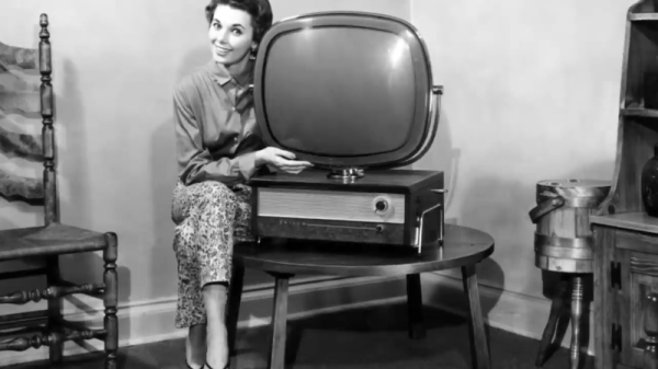
We often read about the minicomputers of the 1960s, and see examples of their use in university research laboratories or medium-sized companies where they might have managed the accounts. It’s tempting though to believe that much of the world in those last decades of the analogue era remained untouched by computing, only succumbing in the decade of the microcomputer, or of the widespread use of the Internet.

What could be more synonymous with the pre-computing age than the mail system? Hundreds of years of processing hand-written letters, sorted by hand, transported by horses, boats, railroads and then motor transport, then delivered to your mailbox by your friendly local postman. How did minicomputer technology find its way into that environment?

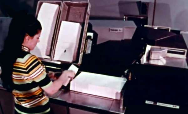
Thus we come to today’s film, a 1970 US Postal Service short entitled “Reading And Sorting Mail Automatically”. In it we see the latest high-speed OCR systems processing thousands of letters an hour and sorting them by destination, and are treated to a description of the scanning technology.

If a Hackaday reader in 2017 was tasked with scanning and OCR-ing addresses, they would have high-resolution cameras and formidable computing power at their disposal. It wouldn’t be a trivial task to get it right, but it would be one that given suitable open-source OCR software could be achieved by most of us. By contrast the Philco engineers who manufactured the Postal Service’s  scanners would have had to create them from scratch.

This they performed in a curiously analogue manner, with a raster scan generated by a CRT. First a coarse scan to identify the address and its individual lines, then a fine scan to pick out the line they needed. An optical sensor could then pick up the reflected light and feed the information back to the computer for processing.

The description of the OCR process is a seemingly straightforward one of recognizing the individual components of letters which probably required some impressive coding to achieve in the limited resources of a 1960s minicomputer. The system couldn’t process handwriting, instead it was reserved for OCR-compatible business mail.

Finally, the address lines are compared with a database of known US cities and states, and each letter is routed to the appropriate hopper. We are shown a magnetic drum data store, the precursor of our modern hard drives, and told that it holds an impressive 10 megabytes of data. For 1970, that was evidently a lot.

It’s quaint to see what seems to be such basic computing technology presented as the last word in sophistication, but the truth is that to achieve this level of functionality and performance with the technology of that era was an extremely impressive achievement. Sit back and enjoy the film, we’ve placed it below the break.

Continue reading “Retrotechtacular: Reading And Sorting Mail Automatically”

Vintage Transistor Powers QRP Transmitter

[Pete Juliano, N6QW] built a 20 M QRP CW transmitter using just a handful of parts. That in itself will not raise any eyebrows, until you find that he built it using one of the very first RF transistors manufactured all the way back in 1955. That’s from before the time most of us were born and not many years after the invention of the transistor in late 1947.

QRP in HAM-speak technically stands for a request to “reduce power” or an offer of “should I reduce power” when appended with a question mark. A QRP transmitter is designed to transmit at really low powers. The accepted upper power limit for QRP transmitters is 5 W, at least for modes like CW using FM or AM modulation. [Pete]’s interest was piqued when he read about a 10 mW 10 M QRP transmitter design in a vintage Radio magazine from the late ’50’s and decided to replicate it. We aren’t sure, but it appears he had a Philco SB-100 RF transistor lying around in his parts bin. The SB-100 was one of the first surface-barrier transistors and could output 10 mW at frequencies up to 30MHz.

[Pete]’s rig was originally putting out 0.4 mW with a 3 V supply, and oscillating at 14.060 MHz in the 20 M band. The design appears to be a simple Colpitts oscillator with just a few parts assembled in dead-bug style on a piece of copper clad laminate. After adding an output transformer, he managed to increase the power output to about 25 mW. Check out [Pete N6QW] sending out a CQ shout out from his QRP transmitter in the video after the break.

If this gets you interested in Amateur Radio, but you are mic-shy, then [Dan Maloney] has some options for you in Shut Up and Say Something: Amateur Radio Digital Modes.

SBF image via Historianbuff CC-BY-SA 3.0, Public Domain
[via Dangerous Prototypes]

Continue reading “Vintage Transistor Powers QRP Transmitter”

Taking Apart A Vintage Oscilloscope

After getting a power supply and a multimeter, the next piece of gear a hacker would want to add to their bench is the oscilloscope. Nowadays, even the cheapest ones cost a few hundred dollars yet pack in the features. At the other end of the scale, if you can pony up close to a  million dollars, you can help yourself to an oscilloscope capable of 100 GHz bandwidth and 240 GS/s sampling rate. With that perspective, it becomes interesting to take a look at this video (embedded below), where [Jack Ganssle] shows us the Philco 7019 Junior Scope which was introduced way back in 1946. It seems the Philco 7019 model was an identical re-badged version of the Waterman Model S-10-A PocketScope.

[Jack] is familiar to all of us as an embedded systems engineer, but in this video he does a teardown of this vintage analog model. He starts off by walking us through the various controls, of which there are not a lot, in this “portable” instrument. At around the 3:40 mark in the video, he’ll make you wince as he uses a screwdriver and hammer combo to smash another ’40’s vintage CRT just so he can show us it’s innards — the electron beam source and the horizontal and vertical deflection plates. The circuit is about as bare-bones as it can get. Besides the CRT, there are just three vacuum tubes. One is the rectifier for the power supply, a second one is used for the vertical amplifier while the third one is the free running horizontal sweep oscillator. There is no triggering option — you just adjust the sweep frequency via a potentiometer as best you can. It does have internal, external and line frequency function selection, but it still requires manual adjustment of the sweep oscillator. There’s no blanking signal either, so the return sweep is always clearly visible. This is evident from the horizontal burn mark on the phosphor of the CRT after decades of use. It’s amusing to see that the vertical position could be adjusted by moving a magnet attached to the side cover.

The Oscilloscope Museum website hosts the Instruction Manual for this model, as well as a sales brochure which makes for very interesting reading after viewing [Jack]’s video.

Thanks, [Itay], for the tip.

Continue reading “Taking Apart A Vintage Oscilloscope”

Vintage Radio Transformed Into Custom PC Case

We see a lot of old radio restoration projects around here, and we have to admit to having mixed emotions about some of them. It seems a shame to go through the effort to lovingly restore a vintage Art Deco case only to stuff it with a Raspberry Pi and Bluetooth. Seems like if you’re going to restore a radio, go all the way and bring the original electronics back to life. But this radio “restoration” avoids that issue altogether by cleverly concealing a full PC build in a vintage radio case.

u3nwbpdClearly a labor of love, [SolomonZaraa]’s two-year effort guts the radio but still manages to pay homage to the original beauty of the 1939 vintage Philco 39-80 “tombstone” portable AM radio. The first design decision was to retask the original tuning dial as an analog thermometer using an Arduino and a servo. Then a new back was added with an extension for the motherboard and PSU, a drive cage was added, and a surprise slot for the DVD drive was built into the speaker grille. Nice brass trim and a good refinishing of the case resulted in an impressive and unexpected presentation.

You don’t have to go far in the Hackaday Wayback machine to find an antique radio with updated audio, but we’re pretty sure this is the first antique radio PC case mod we’ve seen. Nicely done, [Solomon]!

[via r/DIY]

Retrotechtacular: The Future’s So Bright, We’re Gonna Need Photochromic Windowpanes

This is a day in the life of the Shaw family in the summer of 1999 as the Philco-Ford Corporation imagined it from the space-age optimism of 1967. It begins with Karen Shaw and her son, James. They’re at the beach, building a sand castle model of their modular, hexagonal house and discussing life. Ominous music plays as they return in flowing caftans to their car, a Ford Seatte-ite XXI with its doors carelessly left open. You might recognize Karen as Marj Dusay, who would later beam aboard the USS Enterprise and remove Spock’s brain.

The father, Mike Shaw, is an astrophysicist working to colonize Mars and to breed giant, hardy peaches in his spare time. He’s played by iconic American game show host Wink Martindale. Oddly enough, Wink’s first gig was hosting a Memphis-based children’s show called Mars Patrol. He went on to fame with classics such as Tic Tac Dough, Card Sharks, Password Plus, and Trivial Pursuit.

Mike calls up some pictures of the parent trees he’s using on a screen that’s connected to the family computer. While many of today’s families have such a device, this beast is almost sentient. We learn throughout the film that it micromanages the family within an inch of their lives by keeping tabs on their physiology, activities, financial matters, and in James’ case, education.

Continue reading “Retrotechtacular: The Future’s So Bright, We’re Gonna Need Photochromic Windowpanes”