PhD students spend their time pursuing whatever general paths their supervisor has given them, and if they are lucky, it yields enough solid data to finally write a thesis without tearing their hair out. Sometimes along the way they result in discoveries with immediate application outside academia, and so it was for [Paul Bupe Jr.], whose work resulted in a rather elegant and simple bend sensor.
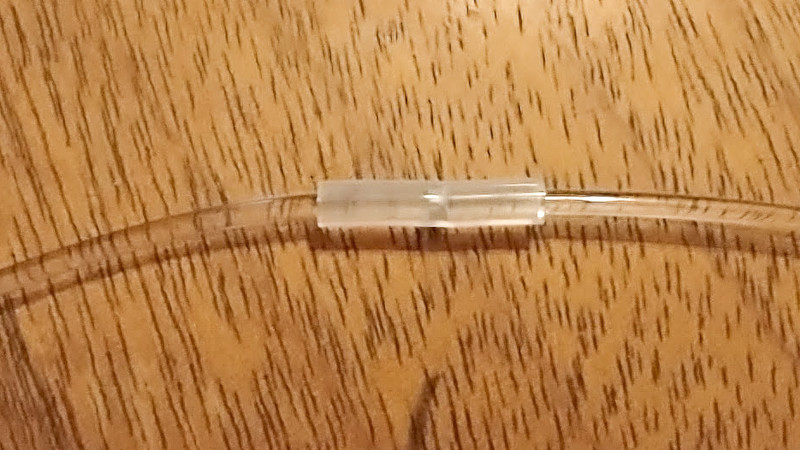
 The original research came when shining light along flexible media, including a piece of transparent 3D printer filament. He noticed that when the filament was bent at a point that it was covered by a piece of electrical tape there was a reduction in transmission, and from this he was able to repeat the effect with a piece of pipe over a narrow air gap in the medium.
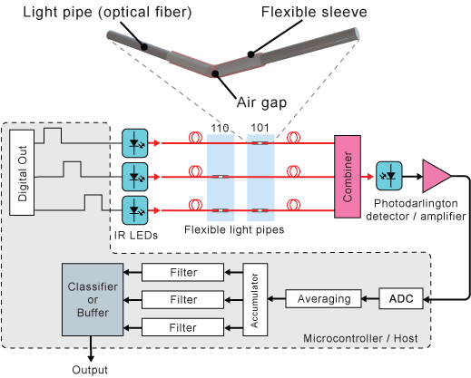
Putting these at regular intervals and measuring the transmission for light sent along it, he could then detect a bend. Take three filaments with the air-gap-pipe sensors spaced to form a Gray code, and he could digitally read the location.
He appears to be developing this discovery into a product. We’re not sure which is likely to be more stress, writing up his thesis, or surviving a small start-up, so we wish him luck.


I have seen experiments in fiber-optic gyroscopes and fiber-interfermeters where a loop is placed to adjust the polarization. I am unsure how new the method is. Also, the Sagnac effect might be an issue with moving assemblies.
Optical fibers have a minimum bending radius that depends on the refractive index in the fiber versus the air (unsleeved fiber).
If you go lower than that limit, you get light leakage that can be measured (you can even use that to intercept what is going on in the fiber without cutting it ;-) )
There exist flexure sensors based on that concept.
Adding an air gap increase the sensitivity (similar to a system of two glass plates at an angle from each other where you can use interferences due to differences in path length, to measure the angle between the plates).
this is the same tech used in the nintendo power glove lol
What’s old is new again, I used to build similar bend sensors for VR.
Some PVC tube, an LED at one end and a light sensor at the other makes for a workable bend sensor for the fingers on your VR gloves.
This is a neat solution but having seen what you can do with even a very old-tech OTDR 20+ years ago I wonder if this would really stack up against a single regular fibre optic strand and a fairly basic OTDR setup.
I could see the application for detecting a bend / degree of bend, but for localising faults I’d think TDR would very quickly become the more practical method.
otdr setup: $$$k+. Resolution: 5mm.
this bend sensor: $10. Resolution: any length / 256 (with 8 leds and wires).
About how much otdr costs: you need to pay $900 just to know what resolution typical equipment should achieve ( https://telecom-info.njdepot.ericsson.net/site-cgi/ido/docs.cgi?ID=SEARCH&DOCUMENT=GR-196& ).