Remember the open source Tengo clone? [jfmateos2] sent in his version, with a custom candles game designed for birthday giving. It’s a nice piece of work, and I love it when we inspire new projects! He sent in a nice write-up of the features he added, so I decided to post it in its entirety:
[Hello, my nick is jfmateos2 and this video http://www.youtube.com/watch?v
The video is in Spanish but subtitled in english. When I first saw the cloned Tengu developed by Alex featured in Hackaday blog, I thought it was a proper project for learning the use of PIC microcontrollers´ specific functions like A/D converters, interrupts and timers. After studying the features of the original Tengu developed by Crispin Jones, I started to specify the requirements of my own clone. I decided to include a basic game intended to transform it into a personalized birthday gift; my sister´s birthday was near.
Its usage is very easy. After connecting PIC-Tengu to a USB port, it will switch on in a sleep state. Blowing on its face he will wake up. Then PIC-Tengu yawns and, if and only if it is the first time we use it, it will start the candles game. The aim of this game is to blow out the candles one by one, so it can become quite boring if the person being honoured is over a certain age, although less painful than pulling his/her ears. Fortunately, my sister is only 25 years old. A personalized scrolling message appears when the game is over. Next, PIC-Tengu starts to imitate every noise it hears. There are four sets of faces available: aquiline-nose, snub-nose, no-nose and Luciano. The active set of faces changes blowing or with a strong noise. Pic-Tengu´s Auditive acuteness is configurable through the back potentiometer. Pressing this button toggles between the imitate mode and the scrolling message mode. If we keep the button pressed more than 2 seconds, PIC-Tengu will reset, recovering the same state as if it had never been used before; this implies that the candle games will appear again after awakening it.
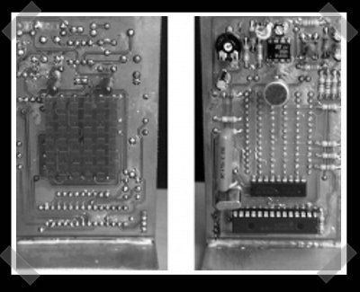
Last, if there is no activity in the imitate mode for more than 5 minutes, PIC-Tengu will fall slept. The brain of this project is a PIC18F2455, whose pins directly activate the LEDs matrix´s rows. There is only one LED column active at any given instant, also determined by the PIC18F2455´s pins, but this time using an intermediary ULN2803. The signal captured by the microphone is amplified using an LM358 before reaching an analog input in the PIC.
The firmware is written in CCS C, and the PIC has been burned using the parallel port version of GTP Lite and WinPIC800.
Electronic schematic, PCB artwork, source code and compiled firmware are available for download in www.villatic.org/carpetaJuanfe
All comments and suggestions are welcome in jfmateos@lycos.es


neat project, but when you say extra usually one can expect tons of links to different projects. (not blaming you for lack of projects or anything, just saying the title might be kinda misleading)
Extra just means another post in addition to the daily hack. (I think)
Thank you very much for featuring my project in your marvellous blog.
I just want to add that the project files are avaiable at http://www.villatic.org/carpetaJuanfe/pictengu.rar
Very cool. I was thinking a great version of this could include a 3.5mm jack as input in addition to the microphone.
I was wondering if it’s possible to have a circuit which would filter out all but the range around the vocals, so the Tengu appears always to be singing whatever gets piped into it.
Just wondering, my niece would love that.
Best presentation of a hack write-up for a long time, kudos
Hi hornhighacedeuce. This was my first prototype.
No I´m working on a SMD version with mini-jack input and a pass-band filter around 3.000 Hz.
Great project – Awesomely thorough documentation
but it seems this link has died:
http://www.villatic.org/carpetajuanfe/pictengu.rar
JF – any way to get that back up and running?
Thnx!
Wow, I couldn’t barely understand his spanish in the included video. He seems to speak ye old-time spanish (think shakesperean). Anywho, nice project.
Hi collin, the problem with the link is that the “j” in “carpetaJuanfe” is an uppercase “j”
One aspect of this project that impresses me is that:
A. it’s a two-sided (home made) board
B. it’s a matrix of discrete LEDs
C. the LEDs have solder connections on both sides of the board
Just aligning a matrix of discrete LEDs is hard – they have a tendency to tilt one way or the other and you have to get their heights even. Combining that with soldering them to both sides of the PCB means he probably spent a lot of time putting it together – unless there’s a trick to it that I’m not aware of.
Hi ledtester.
The two-sided PCB was easy to make using my DIY insolator box with UV leds (http://www.todopic.com.ar/foros/index.php?topic=16795.msg151059#msg1510
59), and a presensibilized bungard positive pcb.
I don´t think it would take me more than 10 minutes soldering the 42 LEDs.
I soldered the leds column by column. The leds are 2mm above the pcb, so
there is a little gap for the iron´s tip. I managed to get the leds
aligned using a couple of wood ruler and pushing the PCB against a wood
board. It´s a bit difficult to explain with words so here you have an
sketch (http://img5
25.imageshack.us/my.php?image=soldarledxx0.jpg). I first soldered the
back face fixing the leds, and later the front face before starting with
the next column.
Now I am working in the SMT enhanced version of PIC Tengu.
My friend Diego Gonzalez has developed and easier to build version of this project, using 2 single-sided PCB instead of 1 double-sided PCB. You can find all the details in http://www.villatic.org/carpetaDiego/Pic_tengu2.rar.
(The “D” in “carpetaDiego” should be an uppercase “D”)