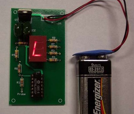
Logic probes can be anything from useful to critical depending on the project, but if you don’t have one already, why not try building one? Instructables has a guide to building a logic probe using a PCB, an assorted lot of resistors, capacitors, regulators, DIP sockets, a 9V battery clip (and 9V battery), and a hex inverter. Instead of using an LED like other simple logic probes, though, this kit uses a 7 segment LED display to show whether logic high (H) or low (L). The schematic makes putting this together only slightly more complicated than snapping Legos together. Of course, the resulting device is not as versatile as a LogicPort logic analyzer, but it is still useful.
13 thoughts on “Logic Probe Kit”
Leave a Reply
Please be kind and respectful to help make the comments section excellent. (Comment Policy)


simple and effective, but I’d think a bicolor led would cost less than the 7-seg. The 7805 will probably drain the 9v batt in no time and get hot doing it.
So basically, whoever created this has managed to take a device that can be built with an led, 2 resistors, a transistor, and a battery, and created a version thats larger, costs more, is more labor intensive to build, and offers exactly the same functionality.
Am I missing something?
NIce little project you have put together.Thanks, regards Colin
Perhaps I got the wrong vibe by the end of the synopsis. “Of course, the resulting device is not as versatile as a LogicPort logic analyzer, but it is still useful.”
I’ve owned the logic analyzer from intronix for a few years. I also own a micronta logic probe, HP Logic Dart, and a Fluke 123 scope meter. Each has its own. And to give the logic probes a little more respect. All these tools are great for their intention. But a logic probe has a place too. The logic analyzer, Logic Dart and Scopemeter take far too long to setup for most quickies. A logic probe gets powered and references signals. visual and audible indications are great and there is not setup over head. I once repaired a pinball controll board using only a logic probe- This was the eye opener that each tool does infact have a very special place in terms of use. Within 5 mins the pinball machine was working. It would have taken that long to setup the other instruments consider the broad range of pins and various signals that needed to be checked.
Don’t take this the wrong way either. The logic port is an excellent tool. But it should not be compared to a logic probe. Apples and Oranges anyone?
amazing that they did it all without any syringes!
@Wolf (post 3)
Would you mind sharing how those few components make a working logic probe? I had a google and only came up with IC based designs :(
Ty!
A 9V battery to 7805 linear regulator is a really bad idea. It will burn that extra 4V off as heat and it will constantly leak about 2-3ma of current. You’ll be replacing that battery a lot. Find a LDO regulator with a low Iq (quiescent current).
@dennis
Basically, you just connect the emitter of a common npn transistor (like a pn2222a) to the probe batteries ground, connect an led and a current limiting resistor in series between the transistors collector and the batteries positive terminal (with the led’s plus side attached to the battery), then attach a second, high value resistor between the transistors base and the logic probe.
The resistor values will depend on the voltage your probes running on, and the voltage you want it to detect, but for a 9v battery and signals above 2v a 470ohm current limiting resistor, and 20k probe would put the max current through the led at 19ma, and keep the current through the probe to less than 1ma. If you wanted to, you could probably go with even higher resistance on the probe and still keep the transistor saturated, but the highest my pot goes is 20k.
If anyone sees that I’m mistaken on any of this feel free to correct me.
Thankyou wolf! Ill give that a go :)
Thoughtful post and well written. Please write more on this if you have time.
This is WAY too complicated and power-hungry for a logic probe with this level of functionality.
80%off on ALL packages with hostgator for this black friday http:// tinyurl com hghosting101
A lot of logic probe schematics exist (this one also good enough) but I did not yet meet with the completely right (or ideal) one for me ;-(
For my taste, the probe has to (must):
– check both CMOS and TTL levels
– be able to recognize & identify 4 (four) states:
— 1. Logical “0”
— 2. Logical “1”
— 3. undefined state (open collector out, high impedance out legs etc.)
— 4(!). mistakenly not connected (non wittingly “suspended” / “float” / “broken”) TTL inputs
– visually apparent signals (see above) close to the very tip
– audible sounded 4 (four) states mentioned above.
Yes, I’ve ordered a thing like ELENCO LP-560 (or “All Sun EM4610”) but they’re not a perfect ones considering my above requirements.
So, I’m making my own scheme… ;-)