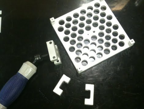
No, the picture above is not a store made steadicam. Rather, a CNC machined one by [Matt]. Interestingly, unlike most steadicams we’ve seen before the gimbal is not the main focus of the design though an aluminum machined gimbal would make us drool. The central idea is allowing for X and Y axis adjustment to get oddly weighted bulky camera’s exact center of gravity. [Matt’s] steadicam is also designed to handle more weight than commercial versions, and (if you already have a CNC) to be much cheaper. There’s no video, but from the skill of craftsmanship we can safely assume it’s as good and level as some of the best.


Nice. Now, I wonder what nice piece of tech one can do without a cnc machine. Nowadays – almost nothing ;<
Gimbals are overrated for steadicams anyway.
Why are you people freaking out about a gimbal? they are brain dead easy to make.
Inline skate wheel, drill two holes and mount loosely a u bracket. attach handle to u bracket, run central rod of steadycam through skate bearing.
Make it in 6 minutes without any real tools.
Typical CNC type loving the X and the Y! Nice bit O machining!
fartface, I’m having trouble visualizing what you’re describing. Got any images of what you’re referring to specifically?
Hmmm… just a thought
If you hog off the material first, THEN drill all those holes, you:
1. Decrease the drill speed cycle time, as you’re drilling trough less material
2. Prevent interrupted cuts by the tool, over all the holes. Aluminum is not that bad, but highter grade steels will have the ability to chip your cutting tool.
Long, even pressured cuts are the goal.
Nice work!
@fartface-that’s not a gimbal, that’s a swivel. A gimbal needs two axes of freedom, at right angles, to actually be a gimbal.
Nice!
I wish my CNC mill could cut that much aluminum (or any, really :P ), although I probably wouldn’t, at least for this project. I would just use thinner stock and attach machined corner pieces.
@Jakob: “Steadier” might be a real word, but you still put a comma-splice in your image mouse-over thingy :P
A couple notes for clarification.
Yes it’s a CNC, but other then the hole pattern (which yes still could have been done manually) I was using it as a manual machine. Honestly this could be done with a drill press and a machinist vise with X and Y axis. But hey use what ya got, right?
Sonny – Take another look at the pictures, I did the steps exactly as you describe.
Amos – The corner pieces were not machined separately since they each have 2 holes in them for the slides and set screws to go in. Just not enough clearance to make them separately attach them and still keep a small(ish) form factor.
Thanks all for the comments, this is my first post to Hackaday, but I’ll be posing more soon!
Sorry, a “steadycam” without an accompanying video is just a fancy camera mount.
Seriously folks. Video.
Otherwise all we have here is some wafflecut aluminum, which a CNC can cut while taking a nap.
Here, look at my scratch built Atari 2600! I mean, it just looks like a bunch of parts in a box, but trust me, it totally works!
I suggest that a single well made self-aligning bearing makes an excellent gimbal for an application like a steadicam. The spherical outer ring raceway provides gimbal like freedom of movement in one small inexpensive part.
Check out http://www.vxb.com/page/bearings/CTGY/Self-aligning for more info on self-aligning bearings.