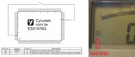
[Craig] cracked open a multimeter to unlock RS232 serial communications that can be used for data logging. There’s a couple of things that make this possible. First of all, the multimeter’s processor is not covered in a black epoxy blob, leaving the pins exposed for hacking. Second, the chip model is known and [Craig] was able to get his hands on the datasheet. One of the pins enables serial output when pulsed low. Touching it to V- even turns on an RS232 icon on the display, as seen above. To make this accessible without opening the case a momentary push button can be added, as well as connector for signal output, and a bit of parsing on the PC side to handle incoming data.


Could you simply tie the pin to V- to have it permanently enabled or does it require a momentary pulse?
that isolated RS232=>USB module would be a handy circuit to have around.
Do they sell another model for more money that includes this functionality? I understand the economic reasoning, but it still bothers me when a company sells two tiers of products where one is merely a crippled version of the other.
Consider instead the perspective that for the intrepid, you are potentially getting a better value than you know when your device has undocumented functionality.
@NatureTM
i have no problem with a company selling crippled products as long as they dont try to stop them being hacked back to full functionality
Operating on the assumption that the pinout of a CyrusTek blob is the same as that of a QFP (which seems likely to be valid from his picture here: http://flashingleds.files.wordpress.com/2010/11/sda2010.jpg), it seems like it would be possible to compile a list of pin counts, connection patterns, and voltages/oscilloscope traces/DSO patterns that would identify a CyrusTek controller with RS232. (A wiki for cheap DMMs describing which ones are using the same ICs would be awesome.) Then, scraping of some soldermask or using exposed pads, we could access the data lines.
Craig, could you please try to find where the RS232 lines on your meter with the RS232 If the they go to pin 45 of the black blob under the question mark, we might be on to something.
Also, what is the maximum resistance through which this pulse can be delivered? If I could try this with, say, a 470k or 2.2M resistor, I’d be much less worried about damaging my meter.
It would appear that the pin in question is a mode toggle pin, thus a momentary button.
Sigh, the URL parser got the ) at the end of my parenthetical note. The URL is:
http://flashingleds.files.wordpress.com/2010/11/sda2010.jpg
@MRE – Yes, I understand that the connection is momentary. However, why not put a resistor in series with the switch like this:
   o            T
   |     ___   ---
   '----|___|--o o--.
   |                |
  ---   2.2M        |
  ---               |
   |                |
  ===              ===
  GND              GND


  o     T
  |    ---
  '----o o---.
             |
             |
            ===
            GND
(created by AACircuit, best viewed in fixed-width)
The second circuit, if accidentally connected to an output pin driving high, could cause damage. I don’t imagine that the first circuit would.
A capacitor is recommended by the datasheet, probably to slow transition time and reduce switch bounce.
@kevin ahh yeah. Good point.
Good work… now time to crack open those cheap DMM at home!
The RSR MY-64 has an epoxy blog labeled ICL 7106, which doesn’t have serial out.
my radioshack multimeter has isolated rs232 communication (its cool how they isolate it also) it is actually much more useful than it sounds
works great for measuring voltage drop on power supplies over time same with mains supply and temperature
you can probably even use the amp meter attachment to chart your houses amp use over time!
@Kevin – The biggest resistor I have on hand is 120k and the enable pulse still works using that.
On my RS232 meter the serial lines trace back to pins 95 & 91, so not the same controller.
Ive wanted to make my meter, an Amprobe 30xr-a, usb connective or add an SD data logger to it for a while now, I just cracked it open and it has the es5108d chip.
The datasheet has bad news :( all I can do extra to mine without doing a whole lot of work is adding capacitor measurement capability which isn’t terribly worth the work.
I cracked open my Kleintools MM1000 and found an fs98o24 IC (datasheet: http://www.ic-fortune.com/upload/Download/FS98O24-DS-10_EN.pdf). Looks to support RS232 and has plenty of test points on the PCB. Might be worth a look.
Years ago I bought a Metex M-3640D ($100), it has a RS232 link and software.
Another data logging possibility is a Texas Instrument Calculator such as the TI-83 with a TI-Connect port and the TI-CBL (Computer Based Laboratory). The CBL can be purchased at TAS
(That Auction Site) for <$40. The CBL will record the data (volts, temp or whatever, the calc will log it which can be downloaded to a PC through the data cable.
here’s my version of the hack for the ‘vichy vc99’ model dmm:
http://www.amb.org/forum/general-diy-discussions-f27/diy-hacking-multimeters-for-rs232-data-logging-output-t1210.html
longer term, I’m planning to buffer the DMM output by an arduino and have it timestamp and relaythe data via wireless xbee or similar to a remote data host (some pc somewhere else in the house).
any hack on sanwa cd800a with FS9711-LP3 inside?
hay heru. do you get any answer of hacking san cd800a with FS9711-LP3