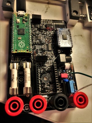
Insides of a multimeter, improved with a custom backlight switch.

Backlight Switch For A Better Multimeter

Frustrated by his Aldi multimeter’s backlight turning off after just 15 seconds, [Steg Steg] took matters into his own hands. His solution? He added a manual toggle switch to control the backlight, allowing it to stay on as long as needed. He began by disassembling the multimeter—removing the outer bumper and a few screws—to access the backlight, labeled “BL.” He identified the voltage regulator outputting 2.8 V, desoldered the red wire, and extended it to install the switch.

On his first try, he successfully drilled a spot for the SPST switch. To fit the switch into the multimeter’s rubber bumper, he used a circular punch, although his second hole wasn’t as clean as the first. Despite this minor setback, the modification worked perfectly, giving him complete control over his multimeter’s backlight without the original 15-second timeout.

Continue reading “Backlight Switch For A Better Multimeter”

Fixing A Busted Fluke While Fighting A Wonky Schematic

Fluke meters have been around for a long, long time. Heck, we’ve got a Fluke 73 that we bought back in 1985 that’s still a daily driver. But just because they’ve been making them forever doesn’t mean they last forever, and getting a secondhand meter back in the game can be a challenge. That’s what [TheHWCave] learned with his revival of a wonky eBay Fluke 25, an effort that holds lessons for anyone in the used Fluke market.

Initial inspection of the meter showed encouragingly few signs of abuse, somewhat remarkable for something built for the military in the early 1980s. A working display allowed a few simple diagnostics revealing that the ammeter functions seemed to work, but not the voltmeter and ohmmeter functions. [TheHWCave]’s teardown revealed a solidly constructed unit with no obvious signs of damage or blown fuses. Thankfully, a service schematic was available online, albeit one with a frustrating lack of detail, confusing test point nomenclature, and contradictory component values.

Despite these hurdles, [TheHWCave] was able to locate the culprit: a bad fusible power resistor. Finding a direct replacement wasn’t easy given the vagaries of the schematic and the age of the instrument, but he managed to track down a close substitute cheap enough to buy in bulk. He searched through 40 units to find the one closest to the listed specs, which got the meter going again. Fixing the bent pin also gave the meter back its continuity beeper, always a mixed blessing.

If you’re in the market for a meter but can’t afford the Fluke name, picking up a busted meter and fixing it up like this might be one way to go. But are they really worth the premium? Well, kinda yes.

Continue reading “Fixing A Busted Fluke While Fighting A Wonky Schematic”

In Praise Of Old Meters

We are spoiled with multimeters today. Even the cheapest meter you will get these days is almost surely digital with a tremendous input impedance. But a few decades ago, meters were almost always analog affairs. To make a precise measurement, you needed a mirror under the meter to ensure you read the needle correctly. Moreover, a common meter wouldn’t have that high of an input impedance. If you spent more, you could get a VTVM and, later, one that used FETs to provide high input impedance. [Peter AA2VG] just picked up a vintage Micronta FET volt-ohm meter to join some of the other new and old meters in his shack. You can check it out in the video below.

[Peter] already has a Simpson and a more modern Fluke meter. The Simpson, however, doesn’t have a tube or FET amplifier. The Fluke is nice, but there is something about the needle on an analog meter. If you aren’t old enough to remember, the Micronta brand was a Radio Shack label.

Continue reading “In Praise Of Old Meters”

Hackaday Prize 2023: AC Measurements Made Easy

When working on simple DC systems, a small low-cost multimeter from the hardware store will get the job done well enough. Often they have the capability for measuring AC, but this is where cheap meters can get tripped up. Unless the waveform is a perfect sinusoid at a specific frequency, their simple algorithms won’t be able to give accurate readings like a high-quality meter will. [hesam.moshiri] took this as a design challenge, though, and built an AC multimeter to take into account some of the edge cases that come up when working with AC circuits, especially when dealing with inductive loads.

The small meter, an upgrade from a previous Arduino version that is now based on the ESP32, is capable of assessing root mean square (RMS) voltage, RMS current, active power, power factor, and energy consumption after first being calibrated using the included push buttons. Readings are given via a small OLED screen and have an accuracy rate of 0.5% or better. The board also includes modern design considerations such as galvanic isolation between the measurement side of the meter and the user interface side, each with its own isolated power supply.  The schematics and bill-of-materials are also available for anyone looking to recreate or build on this design.

With the project built on an easily-accessible platform like the ESP32, it would be possible to use this as a base to measure other types of signals as well. Square and triangle waves, as well as signals with a large amount of harmonics or with varying frequencies, all need different measurement techniques in order to get accurate readings. Take a look at this classic multimeter to see what that entails.

Continue reading “Hackaday Prize 2023: AC Measurements Made Easy”

Digital Microscope With An On-Screen Multimeter

Some things go together, like chocolate and peanut butter. Others are more odd pairings, like bananas and bacon. We aren’t sure which category to put [IMSAI Guy]’s latest find in. He has a microscope with a built-in digital multimeter. You can see the video of the device in operation below.

The microscope itself is one of those unremarkable ten-inch LCD screens with some lights and a USB camera. But it also has jacks for test probes, and the display shows up in the corner of the screen. It is a normal enough digital meter except for the fact that its display is on the screen.

If you had to document test results, this might be just the ticket. If you are probing tiny little SMD parts under the scope, you may find it useful, too, so you don’t have to look away from what you are working on when you want to take a measurement. Although for that, you could probably just have a normal display in the bezel, and it would be just as useful.

At about $180 USD, it’s not exactly an impulse buy. We wonder if we’ll someday see an oscilloscope microscope. That might be something. These cheap microscopes are often just webcams with additional optics. You can do the same thing with your phone. If you don’t need the microscope, but you like the idea, can we interest you in a heads-up meter?

Continue reading “Digital Microscope With An On-Screen Multimeter”

Dentist Tool Hardware Inspires Non-Slip Probe Tips

Cross-pollination between different industries can yield interesting innovations, and a few years ago [John Wiltrout] developed some non-slip meter probe adapters. He recently used our tips line to share some details that you won’t see elsewhere, letting us know how the idea came to be.

It started with [John] being frustrated by issues that will sound familiar: probes did not always want to stay in place, and had a tendency to skid around at the slightest provocation. This behavior gets only more frustrating as boards and components get smaller. John was also frustrated by the general inability to reliably probe through barriers like solder masking, oxidation, and conformal treatments on circuit boards. Continue reading “Dentist Tool Hardware Inspires Non-Slip Probe Tips”

Your Multimeter Might Be Lying To You

Multimeters are indispensable tools when working on electronics. It’s almost impossible to build any but the most basic of circuits without one to test and troubleshoot potential issues, and they make possible a large array of measurement capabilities that are not easily performed otherwise. But when things start getting a little more complex it’s important to know their limitations, specifically around what they will tell you about circuits designed for high frequency. [watersstanton] explains in this video while troubleshooting an antenna circuit for ham radio.

The issue that often confuses people new to radio or other high-frequency projects revolves around the continuity testing function found on most multimeters. While useful for testing wiring and making sure connections are solid, they typically only test using DC. When applying AC to the same circuits, inductors start to offer higher impedance and capacitors lower impedance, up to the point that they become open and short circuits respectively. The same happens to transformers, but can also most antennas which often look like short circuits to ground at DC but can offer just enough impedance at their designed frequency to efficiently resonate and send out radio waves.

This can give some confusing readings, such as when testing to make sure that a RF connector isn’t shorted out after soldering it to a coaxial cable for example. If an antenna is connected to the other side, it’s possible a meter will show a short at DC which might indicate a flaw in the soldering of the connector if the user isn’t mindful of this high-frequency impedance. We actually featured a unique antenna design recently that’s built entirely on a PCB that would show this DC short but behaves surprisingly well when sending out WiFi signals.

Continue reading “Your Multimeter Might Be Lying To You”