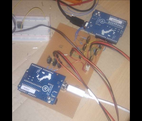
[Simon] improved upon an existing hack by making this Arduino ambient lighting system that has four different color regions. He was inspired by [Roy’s] processing-based setup which we saw a few weeks ago. That system used processing to determine the average color of the currently displayed image, then it displayed the color on a single RGB LED strip. [Simon] was thinking a little bit bigger.
He purchased a lighting strip that could be cut into different sections and then set out to develop his own software for multiple color regions. He had little or no experience with Processing so he went one abstraction layer lower and used Java to code his interface. It’s got a lot of nice settings where you can tweak how, when, and why colors are displayed. In the end he has four independently addressable color strip on the left, right, top-left, and top-right of the screen. The best part is that the Java suite he developed can be used on different platforms, having been already tested on Windows and Linux.


The responsiveness and the spacial awareness of this is quite impressive, but the design in these projects seems a bit flawed. The ambient lighting is directly behind the tv and seems to take away the contrast and focus put on the screen. It would make more sense to place the ambient lighting at the periphery of your vision and behind you pushing your focus into the screen and making you feel enveloped by the action. This design just makes it feel like the screen is bleeding out into the surrounding diffusing and diluting the action.
Call me impressed when someone managed to do it without a computer. This computer versions have to many drawbacks imo, with playback software blocking the software to gather the colors (against piracy..), no support for game consoles etc…
I didn’t read the “hack”; I just think something should be said about the foggy picture in your article. It makes my eyes bleed. I know it was the original photographer’s fault, but you could’ve done /something/… like this, in fact! http://tinyurl.com/4qht97o
You guys should think about hiring someone (*cough*me*cough*) to ‘shop your pictures. :D
Posting this until someone does it :)
1. VGA and DVI both provide RGB analog outputs.
2. Wire each signal into a sub-60Hz butterworth filter (make sure that the inputs are relatively high-Z so they don’t affect your picture)
3. Use the low-passed signals to drive 555-timer-based PWM circuits.
4. Use the PWM to operate RGB LEDs.
One thing I’m not certain of is whether DVI outputs still provide analog signals when connected to digital displays. I would imagine they do, as it’s much simpler to just provide both and let the monitor use what it wants than to actually determine which it’s using and disable the other.
@Amos:
Your picture really looks much better than mine does. I just grabbed my smartphone at that night to take the photos and wanted to get these instructions done so I could go to bed. I actually didn’t even noticed it was that bad, but of course you’re right.
@Kaboof:
You’re right. Some software does not allow to get pixels of their video frame. I got this problem with Power DVD which I used to test different players. But it works fine with other applications like VLC or WMP and on Ubuntu, of course, as well.
@r_d:
That’s what I thought about, too. It’s really complex to set everything up and does not even work with my BluRay Player. But all of my devices are connected with HDMI and I couldn’t grab that signal. If anyone gets that done I would be really impressed and, of course, try to rebuild it. That would be really cool.
@r_d:
excellent idea. The sort of idea that usualy comes into my head. Nice and simple, bare bones and just does the job you asked of it when you want it to do it.
I might take an average singal for each colour over say a 500ms-3second period to cut down on fast flickering of the back ground colour (:
Some caps and voltage comparitors with a 555 for resetting each cap should do nicely with a bit of fiddling.
whole computer to blink LEDs
TV/movies/games just need to provide lighting information from various directions around the camera, so you can make a lighting-based version of surround sound.
Then comes the crappy movies where a glowing purple alien sneaks up behind you.
@CRJEEA
500ms-3second period? taking that long of a sample would mean the scene could have changed from OMG WHITE to a red color – which would render this whole project even more useless.
I’m pretty sure the delay of the LEDs is smoothing enough
@c3p: I don’t think so. You’re modulating the video signal _before_ it goes into the LEDs. If the video signal contains high-frequency components close to or above the PWM frequency (and this will almost always be the case without filtering, as pixels are clocked in the 100MHz range, while the 555 barely approaches this), you will get terrible aliasing. The resulting light will flicker and flash.
You can think of that first low-pass filter as a blur on the image data. Instead of trying to cram the details of each and every pixel into the modulated signal, you’re blurring an entire frame of the video and producing just the overall color.
Hi,
I’m using a HTPC with hardware video acceleration (ION2).
will the software work for me?
thanks,
BenB.